Posted on

Highly efficient desalination using carbon nanotubes

Separating liquid compartments is not only important for generating energy in biological cells, respiration that is, but also for electrochemical cells and desalination through reverse osmosis and other processes. Therefore, scientists and engineers intensively research this field. We have already reported in several posts about promising attempts to make membranes cheaper and more effective. New nanomaterials have also been developed.

As a result of climatic changes caused by global warming, water scarcity is increasingly becoming a problem in many parts of the world. Settlements by the sea can secure their supply by desalinating water from seawater and brackish water sources. The process, however, is very energy intensive.

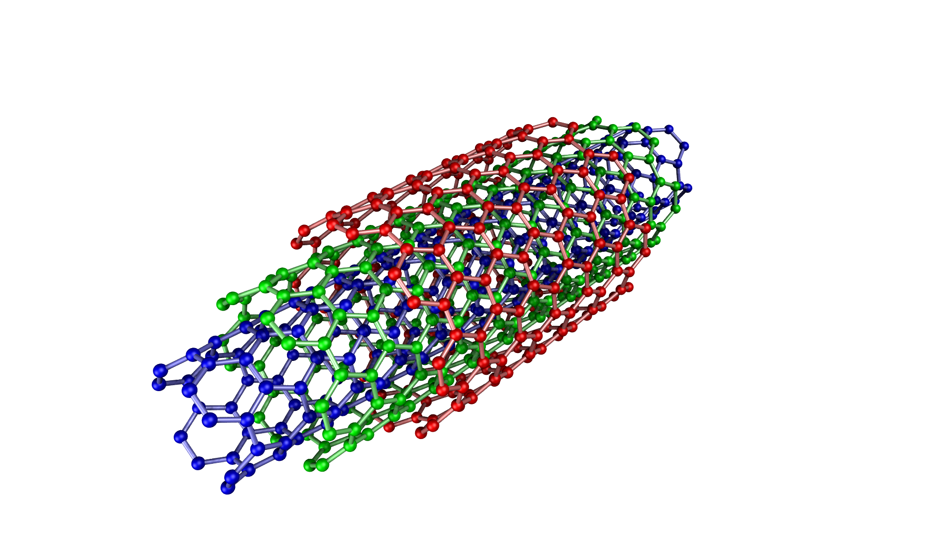
Now, researchers at California’s Lawrence Livermore National Laboratory (LLNL) have developed artificial pores made of carbon nanotubes that remove salt from water so efficiently that they are comparable to already available commercial desalination membranes. These tiny pores are only 0.8 nanometers in diameter. A human hair with a diameter of 60,000 nm. The researchers published the results in the journal Science Advances.

The predominant technology used to remove salt from water is reverse osmosis. A thin-film composite membrane (TCM) is used to separate water from ions. Hitherto the performance of these membranes has, however, been unsatisfactory. There is, for example, always a tradeoff between permeability and selectivity. In addition, exisiting membranes often show insufficient ion repulsion and are contaminated by traces of impurities. This requires additional cleaning stages, which again increase energy costs.

As is so often the case, the researchers got inspired by nature. Biological water channels, also known as aquaporins, are a great model for the structures that can improve performance. These aquaporins have extremely narrow internal pores that compress the water. This enables extremely high water permeability with transport rates of more than 1 billion water molecules per second per pore. Due to the low friction on the inner surfaces, carbon nanotubes represent one of the most promising approaches for artificial water channels.

The research group developed nanotube porins that insert themselves into artificial biomembranes. These engineered water channels simulate the functionality of aquaporin channels. The researchers measured the water and ion transport through their artificial porins. Computer simulations and experiments using the artificial porins in lipid membranes showed improved flux and strong ion repulsion in the channels of carbon nanotubes.

This measurement method can be used to determine the exact value of the water-salt permselectivity in such narrow carbon nanotubes. Atomic simulations provide a detailed molecular view of the novel channels. At Frontis Energy, we are excited about this promising approach and hope to see a commercial product soon.

(Image: Wikipedia)

Posted on

Nanomaterials in bio-electrical systems could improve performance

Since Professor Potter’s discovery of the ability of microbes to turn organic molecules into electricity using microbial fuel cells (MFC) more than a century ago (Potter MC, 1911, Proc Roy Soc Lond Ser B 84:260–276), much research was done to improve the performance. Unfortunately, this did not not produce an economically viable technology. MFCs never made it out of the professors’ class rooms. This may change now that we have advanced nanomaterials available.

The testing of nanomaterials in bio-electrical systems has experienced a Cambrian explosion. The focus usually was on electrodes, membranes, and in the electrolyte with infinite possibilities to find high performing composites. The benefits of such materials include a large surface area, cost savings, and scalability. All are required to successfully commercialize bio-electrical systems. The large-scale commercial application could be wastewater treatment. In our recently published literature survey we discovered that there is no common benchmark for performance, as it is usual in photovoltaics or for batteries. To normalize our findings, we used dollar per peak power capacity as ($/Wp) as it is standard in photovoltaics. The median cost for air cathodes of MFCs is $4,700 /Wp ($2,800 /m²). Platinum on carbon (Pt/C) and carbon nanofibers are the best performing materials with $500 /Wp (Pt/C $2,800 /m²; nanofibers $2,000 /m²).

We found that carbon-based nanomaterials often deliver performance comparable to Pt/C. While MFCs are still far away from being profitable, microbial electrolysis cells already are. With these new carbon-based nanomaterials, MFCs however, are moving closer to become an economic reality. Graphene and carbon nanotubes are promising materials when they are combined with minerals such as manganese or iron oxides. However, the price of graphene is still too expensive to let MFCs become an economic reality in wastewater treatment. The costs of microbial electrolysis, however, are already so low that it is a serious alternative to traditional wastewater treatment as we show in the featured image above. For high strength wastewater, a treatment plant can in fact turn into a power plant with excess power being offered to surrounding neighborhoods. Reducing the costs of microbial electrolysis is accomplished by using a combination of cheap steel and graphite.

Relationship between MEC reactor capacity and total electrode cost including anode and cathode. Errors are standard deviations of four different tubular reactor designs. Anodes are graphite granules and cathodes are steel pipes


Graphite, in turn, is the precursor of graphene, a promising material for MFC electrodes. When graphite flakes are reduced to a few graphene layers, some of the most technologically important properties of the material are greatly improved. These include the overall surface and the elasticity. Graphene is therefore a very thin graphite. Many manufacturers of graphene use this to sell a material that is really just cheap graphite. In the journal Advanced Materials Kauling and colleagues published a systematic study of graphene from sixty manufacturers and find that many high-priced graphene products consist mainly of graphite powder. The study found that less than 10% of the material in most products was graphene. None of the tested products contained more than 50% graphene. Many were heavily contaminated, most likely with chemicals used in the production process. This can often lead to a material having catalytic properties which would not have been observed without contamination, as reported by Wang and Pumera.

There are many methods of producing graphene. One of the simplest is the deposition on a metallic surface, as we describe it in our latest publication:

Single-layer graphene (SLG) and multilayer graphene (MLG) are synthesized by chemical vapor deposition (CVD) from a carbon precursor on catalytic metal surfaces. In a surface-mediated CVD process, the carbon precursor, e.g. Isopropyl alcohol (IPA) is decomposed on the metal surface, e.g. Cu or Ni. In order to control the number of graphene layers formed, the solubility of the carbon precursor on the metal catalyst surface must be taken into account. Due to the low solubility of the precursor in Cu, SLG can be formed. It is difficult to grow SLG on the surface of a metal with a high affinity for the precursor.

Protocol:
The protocol is a cheap, safe and simple method for the synthesis of MLG films by CVD in 30-45 minutes in a chemistry lab. A nickel foil is submersed in acetic acid for etching and then transferred to an airtight quartz tube. The same protects the system from ambient oxygen and water vapor. Nitrogen gas is bubbled through the IPA and the resulting IPA saturated gas is passed through the closed system. The exhaust gases are washed in a beaker with a water or a gas wash bottle. The stream is purged for 5 minutes at a rate of about 50 cc/min. As soon as the flame reaches a Meker burner 575-625 °C, it is positioned under the nickel foil, so that sufficient energy for the formation of graphene is available. The flame is extinguished after 5-10 minutes to stop the reaction and to cool the system for 5 minutes. The graphene-coated Ni foil is obtained.

But how thin must graphite flakes be to behave as graphene? A common idea supported by the International Organization for Standardization (ISO) is that flakes with more than ten graphene layers consist essentially of graphite. Thermodynamics say that each atomic layer in a flake with ten or fewer layers at room temperature behaves as a single graphene crystal. In addition, the stiffness of the graphite flakes increases with the layer thickness, which means that thin graphene flakes are orders of magnitude more elastic than thicker graphite flakes.

Unfortunately, to actually use graphene in bioelectric reactors, you still have to make it yourself. The ingredients can be found in our DIY Shop.