Posted on

Transition between double-layer and Faradaic charge storage in porous carbon nano-material

In electrochemical cells, such as fuel cells or electrolyzers, electric double-layer (EDL) formation occurs on their electrode surfaces. These EDL act as both, capacitors and resistors and impact therefore the performance of electrochemical cells. Understanding the structure and dynamics of EDL formation could significantly improve the performance of, electrochemical systems, for example in energy storage and conversion, including supercapacitors, water desalination, sensors and so forth.

On a planar electrode, electrolyte ions and the solvent are adsorbed at the electrode surface. The resulting capacitance depends on charge, solvation state and concentration. Traditionally, the capacitance of electrochemical interfaces can be divided into two types:

  1. Double-layer capacitance: ions are adsorbed based on their charge. Ion adsorption is non-specific.
  2. Faradaic pseudocapacitance: specific ions are adsorbed, for example through chemical interactions the electrode surface. This may involve charge transfer.

The electrode interface in the most energy application-based technology is, however, not planar but porous. Layer materials in such situations have various degrees of electrolyte confinement and thus different capacitive adsorption mechanisms. Understanding electrosorption in such materials requires a refined view of electrochemical capacitance and charge storage.

A team of researchers from the North Carolina State University, the Paul Sabatier University in Toulouse and the Karlsruhe Institute of Technology reported new insights in electrolyte confinement at the non-planar interfaces in the journal Nature Energy.

Electric double-layer at planar electrodes

The degree of ion solvation (the process of reorganizing solvent and solute molecules) at ideal (planar) electrochemical interfaces determines the ions interaction with the electrodes. There are two distinct cases:

  1. Ions are non-specifically adsorbed: this is the case with strong ion solvation. The electrode’s interactions are primarily electrostatic. This type of interactions can be considered as the induction – charge is induced but not transferred.
  2. Ions are specifically adsorbed: in this case, ions are not solvated and can undergo specific adsorption and chemical bonding to the electrode. This process can be described as charge transfer reaction between the electrode and the adsorbed ion. However, the charge transfer reaction depends on the bonding between the ion and the electrode. This correlates with the state of ion solvation.  Thus, it can be expected that the ion solvation is crucial for understanding the ion-electrode interactions in a nano-confined environment such as porous materials.

Carbon based EDL capacitor – the confinement effect

There is a great interest for understanding the relationship between the porosity of carbon nano-materials and their specific capacitance.

When electric double-layer formation occurs in a nano-confined micro-environment, the EDL capacitor in porous carbon materials deviates from the classic EDL model on flat interfaces. The degree of the ion solvation under confinement is determined by the pore size in nano-porous materials and by the inter-layer distance in layered materials that is, 2D-layer materials.

Confinement of ions in sub-nanometer pores results in their desolvation, leading to the capacitance increase and deviation from the typical linear behavior on the surface area. During negative polarization of porous carbon materials with the pore sizes <1 nm, a decrease of capacitance  is observed. This is due to the ion selection limiting ion transport.

These insights are important for effectively tailoring carbon pore structures and for increasing their specific capacitance. Since carbon material is not an ideal conductor, it is important to consider its specific electric structure. For graphite materials, the availability of the charge carriers increases during the polarization which leads to increased conductivity.

Unified model of electrochemical charge storage under confinement

Since the electrochemical interface in the most technological application is non-planar, the researchers proposed a detailed evaluation and different concept of electrochemical capacitance on such non-ideal interfaces. The team evaluated electrosorption on 2D surfaces and 3D porous carbon surfaces with a continuous reduction in pore size in a step-by-step approach of increasing complexity.

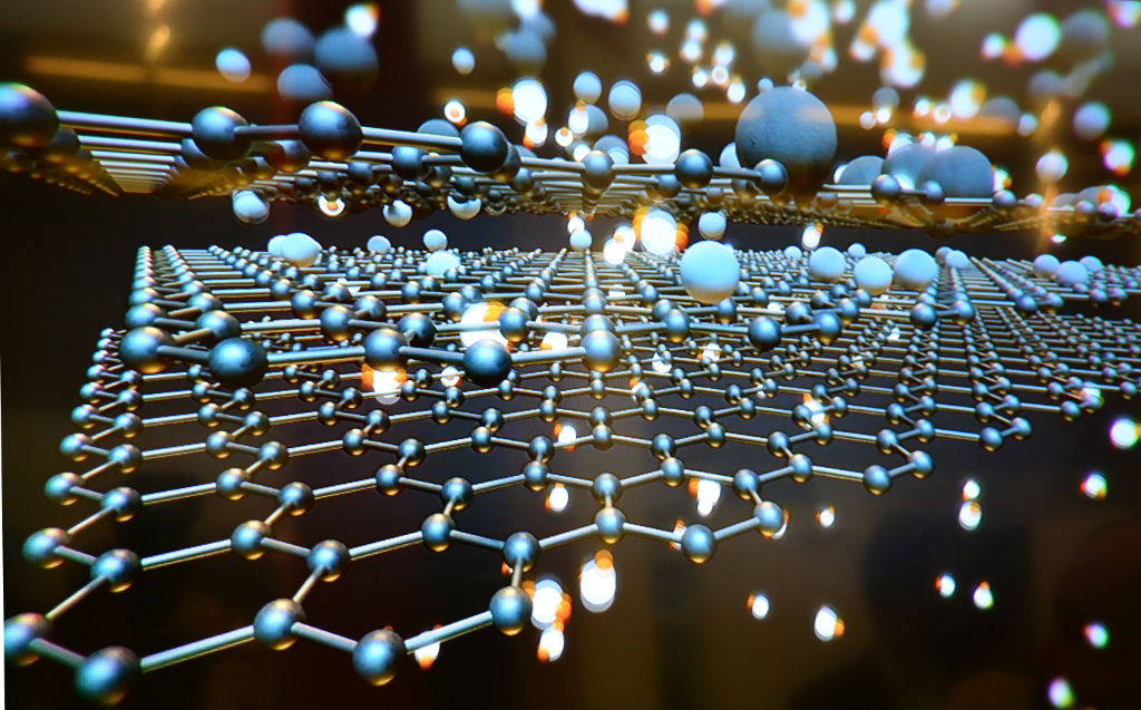
The example provided relates to the charge storage characteristics of lithium ions (Li+) in the graphene sheets of organic lithium-containing electrolytes depending on the number of graphene layers. In a single graphene layer, the capacitive response is potential independent due to the absence of specific adsorption. However, with an increase of graphene sheets, redox peaks emerged that are associated with the intercalation of desolvated lithium ions. Lithium intercalation is responsible for battery wear. The team’s hypothesis was that the transition of solvated lithium ion adsorption on a single graphene sheet into subsequent intercalation of desolvated lithium ions occurs with a continuous charge storage behavior. There can be a seamless transition based on the increased charge transfer between an electrolyte ion and host associated with the extent of desolvation and confinement.

In the presented research, a unified approach was proposed that involves the continuous transition between double-layer capacitance and Faradaic intercalation under confinement. This approach excludes the traditional “single” view of electrochemical charge storage in nano-materials regarded as purely electrostatic or purely Faradaic phenomenon.

The increasing degree of ion confinement is followed by decreasing degree of ion solvation thus the increase ion-host intercalation. This results in a continuum from EDL formation through transitioning state to Faradaic intercalation, typical for EDLC nanomaterial.

Image: Pixabay
Posted on

Humidity-resistant composite membranes for gas separation

Hydrogen (H2) is a lightweight alternative fuel with a high energy density. However, its environmental impact and life cycle efficiency are determined by how it is produced. Today, the main processes of hydrogen production is either by coal gasification or steam reforming of natural gas where in the last step the produced carbon dioxide (CO2) is produced. Usually, this CO2 is released to the environment. The hydrogen produced by these processes lead is called black/brown or grey hydrogen. To improve its carbon footprint, CO2 capture is necessary. This hydrogen is then call blue hydrogen. However, to obtain zero-emission green hydrogen, electrolysis of water using renewable energy is necessary. During the electrolysis process, hydrogen and oxygen are produced on two electrodes (download our more about hydrogen production and utilization as fuel can be found in our latest DIY FC manual).

Climate-related economic pressure for more efficient gas separation processes

The produced hydrogen is not pure in any of the mentioned instances. For example, using steam methane reforming reaction there are many byproduct gases like carbon monoxide, CO2, water, nitrogen and methane gas.

Typically, the CO2 of hydrogen gas is up to 50% contributing to the greenhouse effect caused by burning fossil fuels. Currently, around 80% of CO2 emissions come from fossil fuels. It has been predicted that the concentration of CO2 in the atmosphere will increase up to 570 ppm in 2,100 which increases the global temperature of about 1.9°C.

The traditional processes of gas separation such as cryogenic distillation and pressure swing adsorption have certain disadvantages, for example high energy consumption. Therefore, developing high-quality and low-cost technologies for gas separation is an important intermediate step to produce cheap hydrogen while reducing CO2 emissions.

Application of 2D material towards gas separation

Finding low cost alternatives like membrane-based separation methods for hydrogen-CO2 separation is a potentially lucrative research and it is therefor not surprising that numerous publications have investigated the matter. The various membrane materials for gas separation range from polymeric membranes, nano-porous materials, metal–organic frameworks and zeolite membranes. The goal is to reach a good balance between selectivity and permeance of gas separation. Both are key parameters for hydrogen purification and CO2 capture processes.

A study published the journal Nature Energy by researchers of the National Institutes of Japan, offered a material platform as advanced solution for the separation of hydrogen  from humid gas mixtures, such as those generated by fossil fuel sources or water electrolysis. The authors showed that the incorporation of positively charged nanodiamonds into graphene oxide (GO/ND+) results in humidity repelling and high performance membranes. The performance of the GO/ND+ laminates excels particularly in hydrogen separation compared with traditional membrane materials.

Strategy and performance of new membrane materials

Graphene oxide laminates are considered as step-change materials for hydrogen-CO2 separation as ultra permeable (triple-digit permeance) and ultra-selective membranes. Still, graphene oxide films lose their attractive separation properties and stability in humid conditions.

After lamination, graphene oxide sheets have an overall negative charge and can be disintegrated due to the electrostatic repulsion if exposed to water. The strategy to overcome this obstacle was based on the charge compensation principle. That is, the authors incorporated positively and negatively charged fillers as stabilizing agents, and tested different loadings as well as graphene oxide flake sizes. So-prepared membranes were tested for stability in dry and humid conditions while separating either hydrogen from CO2 or oxygen.

The GO/ND+ composite membranes retained up to 90% of their hydrogen selectivity against CO2 exposure to several cycles and under aggressive humidity test. A GO30ND+ membrane with 30% positively charged nano-diamond particles exhibited exceptional hydrogen permeance with more than 3,700  gas permeatin units (GPU) and high hydrogen-CO2 selectivity. Interestingly, incorporation of negatively charged nano-diamond particles had no stabilizing effect. The researcher attributed this mostly to the generation of macro scale voids in ND systems resulting in the loss of selectivity. This phenomenon is commonly observed in polymer-based nano-composite membranes with poor interfacial interactions

The gas separation properties of the composite membranes were also investigated using an equimolar hydrogen-CO2 feed mixture. The hydrogen permeance decreased by 6% and hydrogen-CO2 selectivity of the GO30ND+ membrane by 13%.

The stability test of the membranes exposure to wet and dry feeds of the equimolar hydrogen-CO2 mixture  and hydrogen-oxygen mixture showed that GO/ND+ membranes were reversible membrane properties. On the other hand, graphene oxide-only membranes could not survive a single complete cycle exposure, becoming fully permeable to both gases. The researchers explained that the advantages of GO/ND+ membranes over graphene oxide-only membranes were caused by changes of the pore architecture such as dimensions and tortuosity, which could be improved by optimizing the nano-diamond loading. This results in better permeability without any notable loss of selectivity.

X-ray diffraction analysis showed that the incorporation of nanodiamonds has two major effects on the membrane microstructure: increasing the overall pore volume and reducing the average lateral size. Both make the membrane structure more accessible for molecular transport.

Nevertheless, this relatively new class of humid-resistant membranes still needs more optimization to compete with current industrial separation processes.

Image: Pixabay / seagul

Posted on

Improving direct ethanol fuel cells by fluorine doping

Direct ethanol fuel cells (DEFCs) are fuel cells that run on ethanol to directly produce electrical power. Despite having much to offer they have not been forayed into. Ethanol can be made from biomass by yeasts and its oxidation products – CO2 and H2O – are hence environmentally friendly. The application of DEFCs could be a lucrative solution for vehicles due to the energy efficiency if mass-produced. Our current infrastructure for combustion fuels is ready for ethanol. DEFC usage would therefore be a sustainable and environment-friendly alternative to current internal combustion engines. Moreover, ethanol is liquid, which facilitates distribution, storage and use.

According to studies sponsored by  International Energy Agency (IEA), DEFCs deliver high power densities, culminating between 50 to 185 mW / cm2. Currently, DEFCs face multiple challenges such as slow redox kinetics, limited performance, and the high cost of electrocatalysts needed for DEFCs.

In a DEFC, the two key reactions are:

  1. Ethanol Oxidation Reaction (EOR)
  2. Oxygen Reduction Reaction (ORR)

Their sluggish rates have prevented widespread adoption of this technology. State-of-the-art DEFCs require expensive platinum-based materials to catalyze these reactions. Yet, they do not completely oxidize ethanol to CO2 to complete the EOR reaction, limiting the energy efficiency. One way to fix this issue is to separate and re-inject the unreacted ethanol. Since this adds more engineering to the fuel cell, a better solution is to find more efficient catalysts. Hence, to realize the true potential of DEFCs, is to find cheaper and more active catalysts for the two reactions in DEFCs.

The researchers at the University of Central Florida and their colleagues experimented on Pd–N–C catalyst and attempted to improve catalyst performance by introducing fluorine atoms. The team used alkaline membranes and platinum-free catalysts. Not only were these more cost-effective but also produced a high power output.

Previous research on electrocatalytic systems revealed that the local coordination environment (LCE) of the electrode surface is pivotal in tuning the activity of electrocatalysts made of carbon-supported metal nanoparticles. The study showed that introducing fluorine atoms in Pd–N–C catalysts regulated the LCE around the Pd, improving both activity and durability for the two key reactions. This improved the catalytic performance, and ultimately the fuel cell’s performance.

The new study demonstrated that fluorine doping rearranged the electron structure of the fuel cell catalyst. This substantially improved power density and ultimately the performance of the DEFC when compared with present-day benchmark catalysts. The experimental results on long-term stability demonstrated promising advancements towards practical applications of such catalysts in DEFCs.

Results

Upon experimental analysis, it was found that the fluorine atoms in the catalyst weakened carbon-nitrogen bond and pushed the N atoms towards palladium. This electron translocation efficiently regulated the LCE of palladium by forming palladium-nitrogen active sites for catalytic reactions.

The N-rich palladium surface promoted carbon-carbon bond cleavage and enabled complete ethanol oxidation. During the ORR, the N-rich palladium surface surface not only weakened CO2 adsorption but also created more accessible catalytic sites for rapid O2 adsorption.

According to the authors, a commonly occurring problem in DEFCs – the inability to complete the two key reactions – has been resolved. Their catalyst enhanced the overall performance of the fuel cell. The addition of fluorine also enhanced the durability of the catalyst by reducing the corrosion of carbon materials as well as inhibiting palladium migration and aggregation.

When the novel catalyst was tested in a DEFC, an output maximum power density of 0.57 W/cm2 was obtained. The fuel cell was stable for more than 5,900 hours. The proposed strategy, when experimented with using other carbon-supported metal catalysts, also gave improved results in activity and stability.

Outlook

The main shortcoming of DEFCs running in the alkaline condition is their durability. Currently, it is not sufficient for practical applications. Moreover, the anion-exchange membranes in use have two issues:

  • Structural stability of membrane is insufficient for long-term use
  • Carbonation occurs in presence of CO2 due to its reaction with hydroxide ions, ultimately degrading the catalyst.

Albeit stable for remarkable 5,900 hours, the membrane was replaced after 1,200 hours in the presented study. Since replacing membranes require complete disassembly of the cell, this is not a long-term practical solution.

Hence, there must be further research on increasing ionic conductivity and stability of anionic membranes for practical use of DEFC in alkaline conditions. Ideally, the hydroxide solution used to increase ionic conductivity is avoided to preserve energy density and reduce the complexity of the device. Solid oxide fuel cells offer a solution for these problems since the fuel is oxidized in gaseous form but their ceramic membrane are too fragile for mobile applications.

The current experiment makes significant strides in improving power density in DEFCs much more than any state-of-the-art DEFCs. The way ahead is further research to overcome these smaller obstacles in the long-term use of anionic membranes.

Experimental analysis

Materials used

Commercial Pd/C (10%, 8 nm Pd particles on activated carbon), as well as Pt/C (20%, 3 nm Pt particles on carbon black), were used as baseline catalysts. Also, Nafion™ solution (5%), carbon paper (TGP-H-060), and anion-exchange membranes (Fumasep FAS-PET-75)

Synthesis of heteroatom X-doped carbon (X–C, X=N, P, S, B, F)

Carbon black with abundant oxygen functional groups and melamine (C3H6N6) were mixed and ground, and finally pyrolyzed. After cooling to room temperature, N–C was obtained by washing with ethanol and water. The same method was used to synthesize P–C, S–C, B–C, and F–C from sodium hypophosphite anhydrous, sulfur powder, boric acid, and polyvinylidene difluoride.

Synthesis of hetero-atom fluorine-doped carbon catalysts

N–C and polyvinylidene difluoride were mixed and ground before adding them into a solution of acetone and water. After ultra sound treatment, the mixture was refluxed in an oil bath until fully dried. The mixture was then pyrolyzed and after cooling to room temperature, the samples were washed with ethanol and ultrapure water, followed by a vacuum to obtain the fluorinated catalyst support. The same method was used for the other precursors.

A microwave reduction method was used to synthesize palladium catalyst on the catalyst support. The content of palladium in all samples was kept at 1.0%, which was determined and double-confirmed by X-ray spectroscopy and inductively coupled plasma.

Electrochemical characterizations

For the electrical measurements, either a glassy carbon ring-disc electrode or rotating ring-disc electrode were used. The Fumasep membrane was used as an anion-exchange membrane, modified to change it to a hydroxide environment.

Reference

Chang et al., 2021, Improving Pd–N–C fuel cell electrocatalysts through fluorination-driven rearrangements of local coordination environment. Nature Energy 6, 1144–1153 https://doi.org/10.1038/s41560-021-00940-4

Image Source: P_Wei, Pixabay

Posted on

Remarkable performance of Fe–N–C cathode electrocatalysts in anion-exchange membrane fuel cells (AEMFC)

Catalysts for low-temperature fuel cells are permanently improved to overcome high costs. Only when low-temperature fuel cells are competitive with internal combustion engines will they be an alternative power source for transportation or even portable devices. The US Department of Energy’s (DOE) milestones for the cost of a light-duty vehicle fuel cell system is $30 per kWnet. However current costs of a proton-exchange membrane (PEM) fuel cells ranges between $45 and $51 kWnet.

Challenged to reduce fuel cell production cost, researchers have suggested changing the fuel cell operating environment from acidic pH to alkaline. This will require to replace PEM by anion-exchange membranes (AEM) in fuel cells. The true advantage of AEM over PEM fuel cells is the cost reduction through cheaper membranes. Additionally, a broader spectrum of materials could be used and the oxygen reduction reaction (ORR) kinetics would be improved. Yet, acidic conditions corrode non-precious metals quickly while at the same time the high loading of platinum group metals (PGM) catalysts  need to be reduced as well.

Synthesis of Fe-N-C electrocatalyst and it structure

Researchers from the University of South Carolina, Columbia (USA) together with their partners recently reported in Nature Energy the remarkable performance of inexpensive Fe-N-C cathode catalysts with single-atom Fe-Nx active sites in AEM fuel cell. The Fe-N-C catalyst was constructed in respect to two important aspects: increase the average pore size (ranging from 5-40 nm, 1 µm) as well as the level of graphitization. Both measures reduce the hydrophobicity of the catalyst layer. To optimize their catalyst’s performance, the researchers went through an iterative process using various material characterization techniques. Energy Dispersive Spectroscopy mapping was used to ensure the catalyst composition was homogeneous. Iron atoms in the catalyst were present as single atoms, which was confirmed by Scanning Transmission Electron Microscopy imaging.

Catalyst performance and integration in AEM fuel cells

The electrochemical analyses carried out by the scientists showed that their Fe-N-C catalyst achieved high ORR activity via four-electron O2 reduction. In this reduction reaction, oxygen is directly reduced to water without the intermediate hydrogen peroxide step. The yield of hydrogen peroxide as function of potential over the entire experimental range was less than 1% – a good result for a non-precious metal catalyst. The current density of the reaction was of 7 mA / cm2.

The Fe-N-C catalyst was used on the cathode of a hydrogen-oxygen AEM fuel cell. An high peak power density of 2 W / cm2 was reported. This performance is the highest reported value for polymer membrane fuel cells (AEM and PEM) using a non-precious metal catalyst. Especially the 4x lower loading of Fe-N-C catalyst compared with previous reports makes this type of fuel cell economically interesting. Moreover, the electrocatalyst was stable at voltages of 0.6 V for more than 100 hours.

To evaluate feasibility of Fe-N-C cathode for more practical application, the fuel cell was tested in the air flow as cathode oxidant. The achieved current density was 3.6 mA / cm2 at 0.1 V with a peak power density of over 1 W / cm2. These results again show the highest reported values in the literature up to date compared to other hydrogen-air AEM fuel cell.

Fuel cell test target DOE-criteria

The cell configuration simulating more realistic operation was intended to benchmark against the DOE targets and the DOE2022 milestones. Cathodes with 0.6 mg Pt / cm2 and a 1 mg Fe-N-C per cm2 were compared. The paired cell was operated under conditions similar to the DOE-defined protocol: 0.9 V iR-free, cell temperature 80°C and 100 kPa partial pressure of O2 and H2. A steady-state current density reached at 0.9 V (iR-free) was approx. 100 mA / cm2. This was more than twice the DOE target.

Finally, the next configuration was designed using the DOE2022 milestones protocol postulating that the total precious metal loading should be less than 0.2 mg Pt / cm2. This was achieved by integrating Fe-N-C cathode with low-loading PtRu/C anodes (0.125 mg PtRu per cm2). This cell reached a peak power density of 1.3 W / cm2 under hydrogen-oxygen operation. Recalculating this value to a specific power output of 16 W per mg Pt results in the highest value of any AEM fuel cell ever reported in the literature.

It has been demonstrated that the Fe-N-C electrocatalyst can compete with noble metal-based catalysts for AEM fuel cells. The reported cell configuration provided remarkable performance in terms of activity and durability under fuel cell condition.

Methodology and electrode preparation

  • Rotating ring disc system – RRDE, was used for evaluation of electrochemical performance for ORR of Fe-N-C catalyst.
  • Fe-N-C catalyst was prepared with higher density of Fe-Nx centers since it has been reported that a higher carbon proportion also results in a higher number of positions in the graphene sheets available for insertion of active sites.
  • For the comparison Pt/C electrode was analyzed.
  • In the electrochemical cell the electrodes were: working electrode – catalyst was cast on the GC disk and stabilized with 5% Nafion® ;
  • Platinum mesh was used as counter electrode and Ag/AgCl as reference electrode, 0.1 M KOH was used as electrolyte.
  • For the tests in anion-exchange membrane fuel cell, gas diffusion electrodes were used: Anode was prepared with low-loading PtRu/C material (0.125 mg PtRu per cm2, 0.08 mg Pt per cm2), while for the cathode Fe-N-C catalyst was used – both were prepared by spraying catalyst ink onto a gas diffusion layer.

Image: iStock

Posted on

Multifunctional iridium-based catalyst for water electrolysis and fuel cells

Most of the world’s energy needs are currently served by fossil fuels. The International Energy Agency (IEA) annual projection indicates that the global energy demand will increase twice by 2040, mostly in emerging markets and developing economies.

To meet increasing global energy demands and to replace depleting fossil fuels, policy makers believe that alternative clean and renewable energy sources are the best solution. Such renewable energy sources can be electricity for solar, wind or geothermal energy as well as hydroelectric power. The latter, however, has reached a certain degree of saturation in fully industrialized countries.

While solar and wind energy are available in most places of the world at more or less reasonable cost, their biggest disadvantage is that they are intermittent, difficult to store and transport, and difficult to tank in cars, planes and ships. Converting solar and wind energy in hydrogen gas could be an elegant way out of this dilemma as the fuel’s resource can be abundant water. Diversifying the energy mix by adding hydrogen at acceptable cost may prove more efficient with a lower environmental footprint as compared to other fuels. Hence, the interest for  water electrolysis and fuel cells  is constantly growing.

Most of today’s hydrogen is produced through steam reforming of natural gas. However, it can also be made from water electrolysis. Electrolysis is two-electrode reactions: the hydrogen evolution reaction (HER) at the cathode and the oxygen evolution reaction (OER) at the anode.

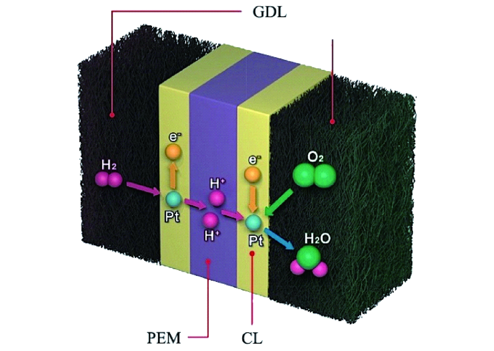
Fuel cells reverse the reaction and harvest electricity produced by fusing the hydrogen and oxygen atoms back together to obtain water. While there are different types of fuel cells, those commonly used with hydrogen as fuel are polymer electrolyte membrane fuel cells, or PEMFC. The PEM acronym is also often used for proton exchange membranes, which can be made of polymers, for example Nafion™.  In PEMFC, energy is liberated through the hydrogen oxidation reaction (HOR) at the anode and oxygen reduction reaction (ORR) at the cathode. To become economically feasible, there are still technical challenges of water electrolyzers and fuel cells to overcome. Some technical problems result in serious system degradation.

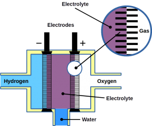
Water is pumped into a fuel cell where two electrodes split it into hydrogen (H2) and oxygen (O2)

A study published in Nature Communications by researcher of Technical University Berlin and the Korea Institute of Science and Technology, suggests using a novel iridium electrocatalyst with multifunctional properties and remarkable reversibility. While iridium also is precious and one of the platinum group metals, the novel Ir-catalyst was designed for the processes where electrochemical reactions change rapidly, such as the voltage reversal of water electrolysis and PEMFC systems. This would integrate the two energy conversion systems in one and therefore be a great economical benefit over existing solutions.

Challenges

Unexpectedly changing operating conditions such as a sudden shut-down of water electrolysis result in increased hydrogen electrode potentials which lead to degradation hydrogen producing electrodes.

In fuel cells, fuel starvation can occur at the anode, leading to voltage reversal. Ultimately, this causes degradation of fuel cell components such as the catalyst support, gas diffusion layer and flow field plates. It has been proposed to introduce a water oxidation catalyst to the anode of the PEMFcs in order to promote OER since it is the reaction that competes with the carbon corrosion reaction.

Design of a unique iridium-based multifunctional catalyst

For the study, a crystalline multifunctional iridium nanocatalyst has been designed considering the mentioned challenges in water electrolysis and fuel cell operation.

The reason why an iridium-based material has been selected is its remarkable OER activity as well as good HER and HOR catalytic activity. It is a superior material for anodes and cathodes in electrolyzers and for anodes of PEMFC. For comparisons, the researchers synthesized two catalysts  using the modified impregnation method: carbon-supported IrNi alloy nanoparticles with high crystallinity (IrNi/C-HT) and with low crystallinity (IrNi/C-LT).

The findings indicated that the surface of IrNi/C-HT had reversibly converted between a metallic character and an oxidic IrNiOx character. Under OER operation that is, anodic water oxidation, the crystalline nanoparticles form an atomically-thin IrNiOx layer. This oxide layer reversibly transforms into metallic iridium when returning towards more cathodic potentials. The reversal allows the catalyst to return to its high HER and HOR activity.

The experiments also revealed that the performance of IrNi/C-LT sharply decrease after carrying out the OER. The catalyst degradation was due to the irreversible destruction of the amorphous IrNiOx surface.

In situ/operando X-ray absorption near edge structure (XANES) and depth-resolving X-ray photoelectron spectroscopy (XPS) profiles, suggested that the thin layers of IrNiOx possess an increase in the number of d-band holes during OER, due to which catalyst IrNi/C-HT exhibited excellent OER activity. As expected, under HER conditions, the thin IrNiOx layer was reversibly converted to metallic surface. The mechanistic study of the reversible catalytic activity of the IrNiOx layer has been additionally analyzed by electrochemical flow-cell using inductively coupled plasma-mass spectrometry (ICP-MS). The results demonstrate that the reversible IrNiOx layers come from a dissolution and re-deposition mechanism.

In addition, the performance and catalytic reversibility of synthetized electrocatalysts were used to perform HOR and OER in a real electrochemical device and tested under fuel starvation of the PEMFC. Using voltage reversal, the fuel cell was converted into an electrolyzer.

Fuel starvation experiments were conducted in a single PEM fuel cell built using IrNi/C-HT and IrNi/C-LT as the catalytically active components in the anode catalyst layer. The initial fuel cell performance of IrNi/C-LT and -HT was lower than that of the commercial Pt/C catalyst due to the lower HOR and metal composition.

Further results demonstrate that IrNi/C-HT catalyst retained its bifunctional catalytic activity, reversibing between HER and OER in a real device. This approach promoted the reversibility of nanocatalysts, which enable a variety of electrochemical reactions and can be used as catalysts to resist the reverse voltage in fuel cells and water electrolysis systems.

At Frontis Energy, we are looking forward to adding the novel iridium catalyst to our Fuel Cell Shop as soon as it becomes available.

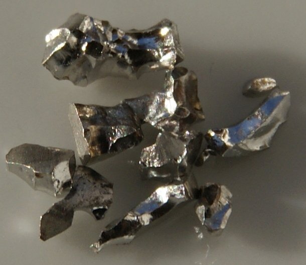
Photo: Iridium / Wikipedia

Posted on

Rapid imaging of ion dynamics in battery materials

Particles in lithium-ion batteries are crucial for releasing positively and negatively charged lithium ions. The migration of these ions is a limiting factor for the batteries’ charge and discharge cycles. To develop fast charging batteries, engineers and scientists need to understand how ions in batteries travel. Now, researchers at the University of Cambridge published in the prestigious journal Nature an imaging approach that follows ion movement in functional battery materials in real-time. This technology helps to better understand how lithium-ion batteries work at sub-micrometer sizes and ultimately to construct batteries that charge in only a few minutes.

Scientists need to understand the ion dynamics of active particles to build better batteries but also other galvanic cells such as fuel cells or electrolyzers. Hitherto, traditional approaches for studying lithium-ion dynamics could not trace the rapid changes that occur in batteries that charge in minutes at sub-micrometer precision.

The problem

In lithium-ion batteries, two porous electrodes (positive and negative) are comprised of active particles: carbon, a metal oxide and a binder. The carbon and metal oxides act as electron conductors, while the binder glues the particles to hold the materials together. An electrolyte separates the two electrodes of the battery and acts as a conduit for ions to travel from one electrode to the other.

Engineers need to image the relevant physical and chemical interactions at least ten times faster than the operation time to track the internal ion dynamics of batteries for each of these processes. This is similar to choosing a camera shutter speed appropriate for filming sports – if the shutter speed is too slow, the camera will generate hazy images. The geometry of the active particles and the structure of the porous electrodes are of particular interest for battery development.

Each battery imaging technique has a unique image capture time, defining which battery functions can be accurately recorded. Previously existing approaches take a few minutes to collect an image; therefore, they can only catch processes that take many hours to complete.

Which is the new concept?

Notably, the researchers’ novel technique takes less than a second to acquire a picture, allowing for considerably faster processes to be studied than previously feasible. As an imaging tool, it is also capable of studying batteries while in use and has a sufficient spatial resolution. This sub micrometer resolution is required to track what happens in an active particle. Furthermore, by comparing the evolution of ion concentration in active particles spatially separated in the electrode, the approach can map ion dynamics at the electrode scale.

Methodology

The research team adapted an optical microscopy approach previously used in biology to follow lithium-ion mobility in active battery materials. This method involves passing a laser beam at electrochemically active battery particles storing or releasing lithium ions and then analyzing the scattered light. As additional lithium is stored, the local concentration of electrons in these particles varies. This changes the scattering pattern. As a result, the local change in lithium concentration correlates with the time development of the scattering signals and can be used to locate the particles.

During charge-discharge cycles, ‘active’ materials in battery electrodes store and release ions. The researchers describe in their publication a real-time imaging approach that uses light scattered from active particles to follow ion concentration changes. The intensity of scattering fluctuates with local ion concentration. In their approach, the evolution of scattering patterns over time indicated the system’s ion dynamics. As additional ions are stored in a particle, the colors of the contours show the change in scattering intensity over the previous 5-second period: red denotes an increase in intensity, while blue suggests a reduction. The shifting patterns correspond to the material’s passage from one phase to the next. When a central domain of one phase shrinks and surrounding domains of another phase grows, broken black lines show phase borders.

Conclusion

The new imaging technique can be used for almost all active materials that store lithium or other ions, suffering electronic changes as the ion concentration changes. Because standard approaches cannot directly track changes in local concentration throughout a particle during fast operation, the time variation of ion concentration in active particles remains poorly understood. The new solution will enable electrochemical engineers to test proposed mechanisms of ion transport in these materials by overcoming the imaging problem.

Limitations to this approach

It should be emphasized that the spatial resolution of the authors’ imaging technique is limited by a basic restriction imposed by the wavelength of the light. Shorter wavelengths are required to resolve finer details. In the presented work, the resolution was around 300 nanometers. Another point to consider is that laser scattering is the result of light interacting with just one object. Another drawback is that scattering results from light interacting with the particle’s first couple of atomic levels. As a result, this method only catches the ion movements in the 2D plane related to these atomic layers. Slower approaches, such as X-ray tomography, can be used to gather 3D information.

Way forward

It will be fascinating to follow up on the authors’ findings for individual particles and investigate porous electrodes under the far-from-equilibrium conditions of fast charging.

This approach could also investigate solid electrolytes, which are intriguing but poorly understood battery materials. Suppose light scattering from solid electrolytes varies with local ion concentration, as it does in active materials. In that case, the approach could be used to map how the ion distribution changes in such electrolytes as electric current travel through them. Other systems involving coupled ion and electron transport, such as catalyst layers in fuel cells and electrochemical gas sensors, could benefit from the optical scattering method as well.

In the future, thorough scattering tests using homogeneous particles could help to quantify the link between the scattering response and lithium-ion concentration. The scattering signals might then be converted to local concentrations using this correlation. However, the link between different materials will not always be the same. Machine-learning approaches could accelerate finding these links and automate light scattering analysis.

The authors’ imaging method also opens up the possibility of measuring chemical and physical (geometric) changes in active particles during battery operation at the same time. The difference between the scattering from a particle and that from other materials in a battery (such as the binder or electrolyte) could be used to determine the particle shape and how it evolves. The time required for light scattering a particle would reveal local changes in lithium concentration. These materials store much more energy than current active materials, and their adoption could reduce battery weight. This would be especially advantageous in electric vehicles, as it would allow for longer driving ranges.

The research provides previously unavailable insights into battery materials working in non-equilibrium situations. Their method for directly monitoring changes in active particles during operation will complement previous approaches that rely on destructive battery tests to infer internal alterations. As a result, it has the potential to transform the battery-design process.

Reference details

Merryweather, et al., 2021 “Operando optical tracking of single-particle ion dynamics in batteries”, Nature, 594, 522–528, doi:10.1038/s41586-021-03584-2

Image: Wikipedia

Posted on

Smart fuel cells catalyzed by self-adjusting anodes improve water management

Hydrogen fuel cells are often regarded as a key element in the green energy transition. Their efficiency is double the thermochemical energy conversion of internal combustion engines. Hydrogen fuel cells convert the chemical energy of hydrogen and oxygen directly into electricity and water. Hence, water plays a central role in fuel cells. It supports ion transport and participates is product of the reaction itself. In an anion exchange membrane fuel cell (AEMFC), for the oxygen reduction reaction to take place, the water in the anode catalyst layer (ACL) must diffuse to the cathode catalyst layer (CCL). In summary, water management is required to remove water from the ACL for higher efficiency of hydrogen diffusion and to balance the water in the entire membrane electrode assembly (MEA).

Significant research efforts have been made to achieve conditions that is suitable for both the anode and cathode in AEMFC. Asymmetric humidification of reactant gases was proposed to be beneficial to achieve well equilibrated water balance between the two electrodes. At higher temperatures, excess anode water evaporates. It also causes deficiencies at the cathode which also requires water to function. To counteract this, a new system that controls the back pressure at the anode and cathode was introduced. However, external control mechanisms (active control) increase the complexity of the system control.

This is where a passive control system involving MEA modification comes into the picture. Moisture control in a fuel cells can be achieved by designing a suitable gas diffusion layer. Adopting different types of hydrophobic materials for the anode and hydrophilic for the cathode can improve overall fuel cell performance. Poly ethylene tetrafluoroethylene (PTFE) copolymer ion exchange membranes, such as Nafion™ have high water mobility. This property can help water back diffusion to avoid anode flooding while preventing dehydration of the cathode. Designing a gradient microstructure or ionomer content within the CCL could also be useful to improve cell performance and durability.

Recent research published in the journal Cell Reports Physical Science addresses these questions. The presented study was carried out to assess a multi-layer CCL design with the gradient capillary force which has a driving effect on water to solve the water balance problem of anodes in AEMFC. For the purpose of the study, platinum on carbon and platinum-ruthenium on carbon were selected as anode catalysts. Ruthenium increases the hydrogen oxidation reaction activity and possesses beneficial structural properties. Water management and performance of AEMFC would be influenced by the structure of the ACL.

Microstructure analysis of ACLs

ACLs composed of different layers of Pt/C and PtRu/C and a mixed version with a similar thickness of around 9-10 µm were analyzed with energy-dispersive X-ray spectroscopy (EDX).

Pt/C ACL had pores of less than 150 nm while PtRu/C catalysts pores ranged between 300-400 nm. The mixed ACL had a pore size <200 nm.

The researchers concluded that Pt/C and PtRu/C ACL had a stratified and gradient pore size distribution spanning across the anion exchange membrane and the gas diffusion layer. The mixed ACL, however, had a homogenous pore structure throughout the MEA.

Membrane electrode assembly using a polymer electrolyte membrane

Moisture adsorption and desorption behavior of ACLs

To investigate moisture adsorption and desorption, the change of the fuel cell’s moisture content was checked with regards to different levels of relative humidity.

It was observed that the moisture content level increased by up to 50% mass weight along with an increase in relative humidity from 20% to 80%.

With an extended equilibrium time for a relative humidity of 80%, the moisture content of Pt/PtRu and PtRu/Pt ACL began to decrease. This was evidence for the self-adjusting water management behavior.

Desorption at a relative humidity of 60% was done. The water content in ACL showed rapid adsorption and slow-release properties at each relative humidity setting.

Physical adjustment of water behavior was observed in PtRu/Pt ACLs. This was attributed to gradient nano-pores and promoted water transport when water was generated within the ACLs during the electrochemical reactions. It would facilitate fuel cells operation at high current density.

Fuel cell performance of ACLs

To assess the structural effect on water management during operation, fuel cell performance was investigated at different relative humidity and temperature levels.

With increasing relative humidity from 40% to 80%, an increase of the maximum power density was observed as well while the temperature remained constant at 50°C. This was due to higher ionic conductivity at high membrane hydration.

At relative humidity of 100%, a maximum power density of the Pt/PtRu MEA and the mixed MEA decreased, however. The inverted MEA version using PtRu/Pt an increase to 243 mW/cm2 was observed. This suggested that the moisture desorption ability of PtRu/Pt MEA promoted mass transfer during fuel cell operation.

At a temperature of 60°C and 100% relative humidity, the maximum power density of PtRu/Pt reached 252 mW/cm2.

A durability test was conducted for PtRu/Pt MEA. It showed that after continuous operation for more than 16 hours at 100 mA/cm2 the voltage drop was <4%.

Conclusion

It became clear from the tests that the PtRu/Pt anode catalyst layer with its homogenous layer had a better self-adjustment capability for fuel cell water management. The gradient nanopore structure of the catalyst layer made it possible to transport water through the capillary effect. Excess water at the anode could either be transported towards the cathode where it would be used for reaction or towards the gas diffusion layer for its removal prevented flooding. Moreover, this catalyst layer made from PtRu/Pt showed better performance abilities too.

At Frontis Energy we think that this could resolve the issues faced with water management in the fuel cells. Since it is a passive control system that involves modifying the design of the fuel cells internally, intricate external systems could be replaced or complemented. The study certainly helps future fuel cell automation as an interesting new aspect of fuel cell design was discovered that could make them smarter.

Reference: Self-adjusting anode catalyst layer for smart water management in anion exchange membrane fuel cells, Cell Reports Physical Science, Volume 2, Issue 3, 24 March 2021, 100377

Posted on

Green alternative to fluorinated membranes in PEM fuel cells

Polymer electrolyte membrane (PEM) fuel cells have high power density, low operational temperatures. If PEM runs on green hydrogen, it doesn’t even emit carbon. But their fabrication requires perfluorinated sulfonic acid (PFSA) polymers as an electrolyte separator membrane and as an ionomer in the electrode, which is quite expensive. Nafion® is the leading commercial PFSA polymer in the market. However, its manufacturing is costly as well as environmentally hazardous. Therefore, low-cost, environmentally friendly PFSA polymer substitutes are the primary goals for the fuel cell scientific community worldwide.

Researchers of the Texas A&M University and Kraton Performance Polymers Inc. experimented using NEXAR ™ polymer membranes in hydrogen fuel cells, studying different ion exchange capacities. NEXAR ™ polymer membranes are commercially available sulfonated pentablock terpolymers. They published the results in the Journal of Membrane Science . Previous studies showed that changing the ion exchange capacity, that is, the degree of sulfonation of NEXAR ™ membranes can alter the nanoscale morphology and significantly affect mechanical properties. This may influence fuel cell performance. Hence, this polymer may be used as a membrane alternative to Nafion® in fuel cells.

Experimental procedure

  1. Materials under consideration: three different variants of the polymer were taken up each with different Ion Exchange Capacities (IECs: 2.0, 1.5, and 1.0 meq / g), which were named NEXAR ™ -2.0, NEXAR ™ -1.5, and NEXAR ™ – 1.0 respectively.
  2. NEXAR ™ membrane preparation: NEXAR ™ membranes were fabricated by casting the NEXAR ™ solutions onto a silicon-coated Mylar PET film using an automatic film applicator under ambient conditions. Two different sizes were manufactured for measuring mechanical properties and conductivity.
  3. NEXAR ™ membrane characterization: mechanical properties using the size 25 mm (L) x 0.5 mm (W) membrane as test pieces were determined and for proton conductivity test pieces of size 30 mm (L) x 10 mm (W) were tested upon.
  4. Nafion® electrode fabrication: conventional Nafion® electrodes were also fabricated as controls to conduct simultaneous tests.
  5. NEXAR ™ electrode fabrication: NEXAR ™ electrodes were prepared in 2 ways for the 2-part study, each with a different composition.
  6. Electrode characterization: electrode profiling was done using a scanning electron microscopy (SEM).
  7. Membrane electrode assembly (MEA) and fuel cell tests: MEAs were fabricated by placing the membrane in between two catalyst-coated gas diffusion layers (anode and cathode) and heat pressing. The entire fuel cell assembly consisted of an MEA, two gaskets, and two flow plates placed between copper current collectors followed by end plates all held together by bolts. Fuel cell performance tests were conducted under ambient pressure with saturated (100% RH) anode and cathode flow rates of 0.43 L / min hydrogen and 1.02 L / min oxygen respectively.
  8. Electrochemical impedance spectroscopy (EIS): electrochemical impedance spectroscopy was performed after the fuel cell tests and the results analyzed.

Results

NEXAR ™ -2.0 and NEXAR ™ -1.5 had a similar proton conductivity at all temperatures, suggesting that there is a maximum limit in proton conductivity. On the contrary, NEXAR ™ membranes, when compared to Nafion® NR-212 membranes , have sufficient proton conductivity to translate into high power density hydrogen fuel cell performance.

However, NEXAR ™ -2.0 and NEXAR ™ -1.5 membranes (with Nafion® as Ionomer) did not exhibit expected fuel cell performance at all fuel cell operating conditions (temperature, pressure, voltage and humidity). Surprisingly, the NEXAR ™ -1.0 membrane (with Nafion® as Ionomer) showed expected fuel cell performance across all fuel cell operating conditions and comparable power densities to Nafion® , suggesting that NEXAR ™ -1.0 may be a viable alternative to Nafion® in hydrogen fuel cells.

During fuel cell operation the NEXAR ™ -1.0 / NEXAR ™ -1.0 membrane-ionomer was thermally and mechanically stable. These results were supported by the power density results, where MEAs with NEXAR ™ -1.0 membrane-ionomers performed better than all the other MEAs.

From the above-mentioned results it became evident that the NEXAR ™ -1.0 variant was the optimal contender to substitute current state-of-the-art PFSA polymers.

Further, to understand the impact of the NEXAR ™ -1.0 ionomer on fuel cell performance, the composition of the ionomer and solvent mixture ratios in the catalyst ink solution were modified and investigated. Results suggested that NEXAR ™ -1.0 as an ionomer behaves similarly to Nafion® ionomers in fuel cell electrodes.

SEM analysis suggested that the amount of ionomer has a significant impact on the binding of ionomer to the catalyst particles, and consequently on the catalyst layer morphology. Therefore, there is an optimum catalyst / ionomer ratio of 2/1 for the Pt / C ionomer using NEXAR ™ -1.0 in fuel cell electrodes.

Conclusions

Ultimately, NEXAR ™ -1.0 is a potentially commercially viable greener substitute to Nafion® as a membrane and ionomer in PEM Fuel cell applications due to its high conductivity, however; alternative block compositions may improve the properties of the polymer to minimize resistances within the fuel cell to match the performance of Nafion® .

Overall Nafion® / Nafion® MEAs still showed the highest fuel cell performance when overall performance was taken into account but alternative hydrocarbon-based polymer compositions for the NEXAR ™ Polymer might provide a future non-fluorinated polymer as a  Nafion® substitute for PEM fuel cells .

Way forward

More analysis is required to perhaps get an accurate approximation of what variant of the NEXAR ™ polymer might cut the mark, future research may be focused upon exploring variants of Ion Exchange Capacities ranging from say 1 meq / g to 1.5 meq / g. But for now, it can be said that NEXAR ™ polymer shows promise as a viable replacement as a non-fluorinated membrane, and perhaps further research with more iterations of mechanical specs as well as chemical specs of the material we might witness a breakthrough.

Reference: https://doi.org/10.1016/j.memsci.2021.119330 : Sulfonated pentablock terpolymers as membranes and ionomers in hydrogen fuel cells , Journal of Membrane Science, 2021, 119330

Posted on

Highly durable platinum-palladium-based alloy electrocatalyst for PEM fuel cells

To decrease the consumption of fossil fuel-derived energy for transportation, proton exchange membrane fuel cells (PEMFCs) are one of the most promising clean power sources. Their performance, however, strongly depends on the efficiency and durability of the electrocatalyst used for the hydrogen and oxygen reactions occurring at the electrodes. Noble metals such as platinum and gold are still considered as the most efficient catalysts. At the same time, their high cost and scarcity are major road blocks for scale commercialization of these energy devices.

Various solutions of catalyst design are intensively investigated in order to make this technology economically successful. Searching for high catalyst activity and durability for fuel cells is in focus of current research and development. To date, state-of-the-art electrocatalysts are based on carbon materials with varying platinum loadings.

Ultra-high active platinum group metal (PGM) alloy catalyst

Although, recent research reported ultra-high activity of some metal alloy catalysts, problems still remain. Some of these issues are related to utilization of high atomic percentages of PGM (sometimes up to 75% Pt), poor durability and performance under industrial conditions. In search for new solutions, researchers of the State University of New York at Binghamton, USA, and their collaborators reported a new design in journal Nature Communication: a highly-durable alloy catalyst was obtained by alloying platinum and palladium at less than 50% with 3d-transition metals (Cu, Ni or Co) in ternary compositions.

They addressed the problem of severe de-alloying of conventional alloy catalysts under the operating conditions, resulting in declining performance. For the first time, dynamic re-alloying as a way to self-healing catalysts under realistic operating conditions has been demonstrated to improve fuel cell durability.

Alloy combination and composition

The wet-chemical method was used for synthesis of Pt20PdnCu80−n alloy nanoparticles with the desired platinum, palladium and copper percentages. The selected set of ternary alloy nanoparticles with tunable alloy combinations and compositions, contained a total content of platinum and palladium of less than 50%, keeping it lower than current PGM-based alloy catalysts. The incorporation of palladium into platinum nanomaterials enabled a lower degree of de-alloying and therefore better stability. Additionally, palladium is a good metal partner to platinum due to their catalytic synergy and their resistance to acid corrosion.

To reduce the need for platinum and palladium core catalysts, a third, non-noble transition metal played a central role in the catalytic synergy of alloying formation. Non-noble metals such as copper, cobalt, nickel or similar were used. The platinum-palladium alloy with base metals allowed the researchers to fine tune the thermodynamic stability of the catalysts.

Morphology and phase structure

The thermochemical treatment of carbon-supported nanoparticles was crucial for the structural optimization. The metal atoms in the catalytic nanoparticles were loosely packed with an expanded lattice constant. The oxidative and reductive treatments of the platinum-palladium alloy (PGM <50%) allowed a thermodynamically stable state in terms of alloying, re-alloying and lattice strains. The re-alloying process not only homogenized the inhomogeneous composition by inter-diffusion upon calcination of nanoparticles, but also provided an effective pathway for self-healing following de-alloying.

Single face-centered cubic type structures were observed in Pt20PdnCu80–n nanoparticles (n = 20, 40, 60, 80) nanoalloys. Copper-doping of platinum-palladium alloys reduced the lattice constant effectively, as shown by high energy X-ray diffraction. Maximized compressive strain and maximized activity of the Pt20Pd20Cu60 catalyst confirmed strong correlation between the lattice constants and the oxygen reduction activity.

The researchers demonstrated that the thermodynamically-stable Pt20Pd20Cu60/C catalyst exhibited not only the largest compressive strain after 20,000 cycles, but also high activity and high durability. The discovery that the alloy catalyst remains alloyed under fuel cell operating condition is in sharp contrast to the fully de-alloyed or phase-segregated platinum skin or platinum shell catalysts reported in almost all current literature.

The significance in understanding of the thermodynamic stability of the catalyst system is a potential paradigm shift of design, preparation, and processing of alloy electrocatalysts.

(Photo: Pixabay)


Posted on

Solid oxide fuel cells convert methane gas recovered from groundwater

Solid oxide fuel cells (SOFCs) are highly efficient energy conversion devices and have low operating costs. They work at a temperature range of 800 to 1,000 degrees Celsius. This allows for the possibility of using internal conversion of hydrocarbon fuels into hydrogen. Methane, methanol, petroleum, and other hydrocarbons can be converted to hydrogen (H2) directly within the fuel cell.

SOFCs have a number of additional advantages over traditional combustion engines or other types of fuel cells. For example, the high exhaust heat (over 800 degrees Celsius) makes them a useful application in the industry for cogeneration of electricity and heat. Because of combined cycles, high efficiency for electricity production can be achieved. In addition, due to the modular nature of SOFCs, they offer flexible planning of power generation capacity. This way, the use of SOFCs results in a further reduction of carbon dioxide emission.

The greatest advantage of SOFCs is that they can be operated with hydrocarbon fuels such as methane (CH4, the main component of natural gas). The direct use of methane eliminates the need for pre-reformers, thus reducing the complexity, size, and cost of the overall SOFC system.

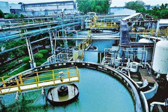
Methane can be recovered from the decay of organic waste in municipal solid waste landfills, drinking water treatment plants, etc. The gas can also be recovered from groundwater because of the naturally occurring anaerobic degradation of organic matter in the subsurface or the infiltration of methane from natural gas reservoirs.

A research team from the Delft University of Technology assumed that the gas collected from groundwater treatment can be effectively used as fuel in SOFCs and put their hypothesis to a test. They published their results in the journal Journal of Cleaner Production. Currently, the methane recovered from the Drinking Water Treatment Plant (DWTP) of Spannenburg, Netherlands is either released into the atmosphere or flared, wasting a precious resource and contributing to further greenhouse emission in the form of CO2.

SOFCs provide the cleanest of the viable solutions of converting recovered methane into electrical energy, which, in turn, can be utilized by the DWTP. This process will decrease the power demands and simultaneously reduce the greenhouse gas emissions of the DWTP.

The entire process was divided into the following steps:

  1. Methane was recovered from groundwater: The groundwater was pumped from the deep-wells directly to a system of vacuum towers, which remove 90% of the dissolved gas using a near vacuum of 0.2 bar.
  2. Subsequent treatment by plate aeration was done to remove the remaining 10% of methane in the groundwater.
  3. Tower aeration used to further remove CO2 before pellet softening process to lower hardness.

Recovered gas sampling:

200 mL of the recovered gas enriched in methane was used to determine the concentration of CH4, H2, Oxygen (O2), nitrogen (N2), carbon monoxide (CO), and CO2.

SOFC set up & thermodynamic approach:

A SOFC test station was used to carry out the experiments. The methane rich gas was fed to the anode and the open circuit potential was logged. Methane must be reformed to hydrogen and CO before electricity can effectively be generated in an SOFC.

Results:

The main components in the sampled gas were methane and CO2 with concentrations of 71 and 23 mol%, respectively. Additionally, the recovered gas contained 9 ppm of hydrogen sulphide (H2S), which can permanently reduce the cell performance of an SOFC. Hydrogen sulphide was effectively removed (<0.1 ppm) with impregnated activated carbon

The use of CH4 recovered from the groundwater in an SOFC helps to mitigate the greenhouse gas emissions and improve the sustainability of DWTPs. The recovered methane gas of the Spannenburg DWTP can be used to run a 915 kW SOFC system. This can supply 51.2% of the total electrical power demand of the plant and decreases greenhouse gas emissions by 17.6%, which is around 1794 tons of CO2.

The annual power generation of the SOFC system can be 8 GWh, which is about 3 GWh more than that produced by an internal combustion engine such as a gas turbine or piston engine.

In the future, the researchers will conduct a long-term tests to determine the safe operating condition of SOFC with respect to the carbon deposition issue. These tests will be extended to the SOFC stack level and pilot plant (in the range of a few kW systems)

(Photo: Indiamart)

Reference: https://doi.org/10.1016/j.jclepro.2021.125877 (A solid oxide fuel cell fueled by methane recovered from groundwater, 2021)