At Frontis Energy we have spent much thought on how to recycle CO2. While high value products such as polymers for medical applications are more profitable, customer demand for such products is too low to recycle CO2 in volumes required to decarbonize our atmosphere to pre-industrial levels. Biofuel, for example from field crops or algae has long been thought to be the solution. Unfortunately, they require too much arable land. On top of their land use, biochemical pathways are too complex to understand by the human brain. Therefore, we propose a different way to quickly reach the target of decarbonizing our planet. The procedure begins with a desired target fuel and suggests a microbial consortium to produce this fuel. In a second step, the consortium will be examined in a bio-electrical system (BES).
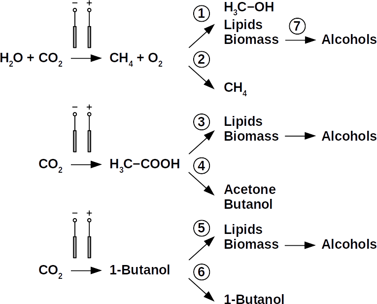
CO2 can be used for liquid fuel production via multiple pathways. The end product, long-chain alcohols, can be used either directly as fuel or reduced to hydrocarbons. Shown are examples of high level BEEF pathways using CO2 and electricity as input and methane, acetate, or butanol as output. Subsequent processes are 1, aerobic methane oxidation, 2, direct use of methane, 3 heterotrophic phototrophs, 4, acetone-butanol fermentation, 5, heterotrophs, 6, butanol direct use, 7, further processing by yeasts
Today’s atmospheric CO2 imbalance is a consequence of fossil carbon combustion. This reality requires quick and pragmatic solutions if further CO2 accumulation is to be prevented. Direct air capture of CO2 is moving closer to economic feasibility, avoiding the use of arable land to grow fuel crops. Producing combustible fuel from CO2 is the most promising intermediate solution because such fuel integrates seamlessly into existing urban infrastructure. Biofuels have been explored intensively in recent years, in particular within the emerging field of synthetic biology. However tempting the application of genetically modified organisms (GMOs) appears, non-GMO technology is easier and faster to implement as the required microbial strains already exist. Avoiding GMOs, CO2 can be used in BES to produce C1 fuels like methane and precursors like formic acid or syngas, as well as C1+ compounds like acetate, 2-oxybutyrate, butyrate, ethanol, and butanol. At the same time, BES integrate well into urban infrastructure without the need for arable land. However, except for methane, none of these fuels are readily combustible in their pure form. While electromethane is a commercially available alternative to fossil natural gas, its volumetric energy density of 40-80 MJ/m3 is lower than that of gasoline with 35-45 GJ/m3. This, the necessary technical modifications, and the psychological barrier of tanking a gaseous fuel make methane hard to sell to automobilists. To produce liquid fuel, carbon chains need to be elongated with alcohols or better, hydrocarbons as final products. To this end, syngas (CO + H2) is theoretically a viable option in the Fischer-Tropsch process. In reality, syngas precursors are either fossil fuels (e.g. coal, natural gas, methanol) or biomass. While the former is obviously not CO2-neutral, the latter competes for arable land. The direct conversion of CO2 and electrolytic H2 to C1+ fuels, in turn, is catalyzed out by electroactive microbes in the dark (see title figure), avoiding food crop competition for sun-lit land. Unfortunately, little research has been undertaken beyond proof of concept of few electroactive strains. In stark contrast, a plethora of metabolicstudies in non-BES is available. These studies often propose the use of GMOs or complex organic substrates as precursors. We propose to systematically identify metabolic strategies for liquid bio-electrically engineered fuel (BEEF) production. The fastest approach should start by screening metabolic databases using established methods of metabolic modeling, followed by high throughput hypothesis testing in BES. Since H2 is the intermediate in bio-electrosynthesis, the most efficient strategy is to focus on CO2 and H2 as direct precursors with as few intermediate steps as possible. Scalability and energy efficiency, economic feasibility that is, are pivotal elements.
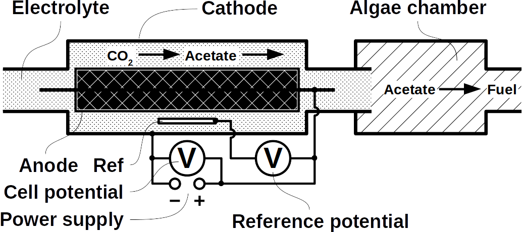
First, an electrotrophic acetogen produces acetate, which then used by heterotrophic algae in a consecutive step.
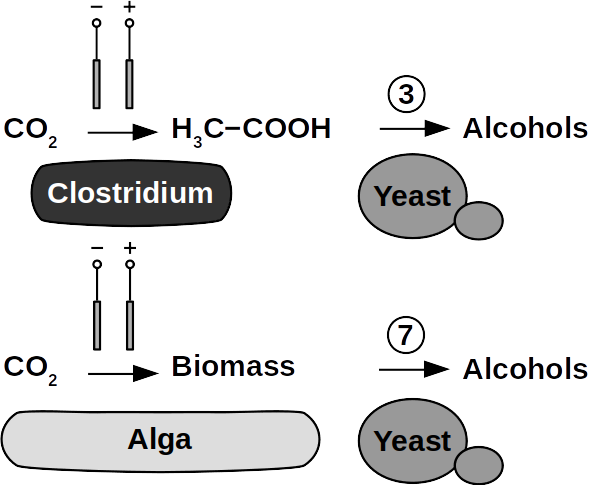
Possible pathways for BEEF production involving Clostridium, 3, or heterotrophic phototrophs, 7, further processing by yeasts
Yeasts are among the microorganisms with the greatest potential for liquid biofuel production. Baker’s yeast, (Saccharomyces cerevisiae) is the most prominent example. While known for ethanol fermentation, yeasts also produce fusel oils such as butane, phenyl, and amyl derivate aldehydes and alcohols. Unlike ethanol, which is formed via sugar fermentation, fusel oil is synthesized in branched-off amino acid pathways followed by aldehyde reduction. Many enzymes involved in the reduction of aldehydes have been identified, with alcohol dehydrogenases being the most commonly observed. The corresponding reduction reactions require reduced NADH but it is not known whether H2 produced on cathodes of BES can be involved.
Clostridia, for example Clostridium acetobutylicum and C. carboxidivorans, can produce alcohols like butanol, isopropanol, hexanol, and ketones like acetone from complex substrates (starch, whey, cellulose, etc. ) or from syngas. Clostridialmetabolism has been clarified some time ago and is different from yeast. It does not necessarily require complex precursors for NAD+ reduction and it was shown that H2, CO, and cathodes can donate electrons for alcohol production. CO2 and H2 were used in a GMO clostridium to produce high titers of isobutanol. Typical representatives for acetate production from CO2 and H2 are C. ljungdahlii, C. aceticum, and Butyribacterium methylotrophicum. Sporomusa sphaeroides produces acetate in BES. Clostridia also dominated mixed culture BESs converting CO2 to butyrate. They are therefore prime targets for low cost biofuel production. Alcohols in clostridia are produced from acetyl-CoA. This reaction is reversible, allowing acetate to serve as substrate for biofuel production with extracellular energy supply. Then, energy conservation, ATP synthesis that is, can be achieved from ethanol electron bifurcation or H2 oxidation via respiration. While possible in anaerobic clostridia, it is hitherto unknown whether electron bifurcation or respiration are linked to alcohols or ketone synthesis.
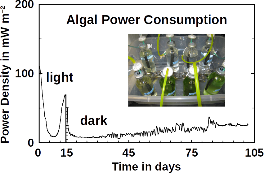
Phototrophs like Botryococcus produce C1+ biofuels as well. They synthesize a number of different hydrocarbons including high value alkanes and alkenes as well as terpenes. However, high titers were achieved by only means of genetic engineering, which is economically not feasible in many countries due to regulatory constrains. Moreover, aldehyde dehydration/deformylation to alkanes or alkenes requires molecular oxygen to be present. Also the olefin pathway of Synechococcus depends on molecular oxygen with the cytochrome P450 involved in fatty acid decarboxylation. The presence of molecular oxygen affects BES performance due to immediate product degradation and unwanted cathodic oxygen reduction. In contrast, our own preliminary experiments (see title photo) and a corrosion experiment show that algae can live in the dark using electrons from a cathode. While the enzymes involved in the production of some algal biofuels are known (such as olefin and aldehyde deformylation), it is not known whether these pathways are connected to H2 utilization (perhaps via ferredoxins). Such a connection would be a promising indicator for the possibility of growing hydrocarbon producing cyanobacteria on cathodes of BES and should be examined in future research.
At Frontis Energy we believe that a number of other microorganisms show potential for BEEF production and these deserve further investigation. To avoid GMOs, BES compatible co-cultures must be identified via in silico metabolic reconstruction from existing databases. Possible inter-species intermediates are unknown but are prerequisite for successful BES operation. Finally, a techno-economical assessment of BEEF production, with and without carbon taxes, and compared with chemical methods, will direct future research.
In electrochemical cells, such as fuel cells or electrolyzers, electric double-layer (EDL) formation occurs on their electrode surfaces. These EDL act as both, capacitors and resistors and impact therefore the performance of electrochemical cells. Understanding the structure and dynamics of EDL formation could significantly improve the performance of, electrochemical systems, for example in energy storage and conversion, including supercapacitors, water desalination, sensors and so forth.
On a planar electrode, electrolyte ions and the solvent are adsorbed at the electrode surface. The resulting capacitance depends on charge, solvation state and concentration. Traditionally, the capacitance of electrochemical interfaces can be divided into two types:
Double-layer capacitance: ions are adsorbed based on their charge. Ion adsorption is non-specific.
Faradaic pseudocapacitance: specific ions are adsorbed, for example through chemical interactions the electrode surface. This may involve charge transfer.
The electrode interface in the most energy application-based technology is, however, not planar but porous. Layer materials in such situations have various degrees of electrolyte confinement and thus different capacitive adsorption mechanisms. Understanding electrosorption in such materials requires a refined view of electrochemical capacitance and charge storage.
A team of researchers from the North Carolina State University, the Paul Sabatier University in Toulouse and the Karlsruhe Institute of Technology reported new insights in electrolyte confinement at the non-planar interfaces in the journal Nature Energy.
Electric double-layer at planar electrodes
The degree of ion solvation (the process of reorganizing solvent and solute molecules) at ideal (planar) electrochemical interfaces determines the ions interaction with the electrodes. There are two distinct cases:
Ions are non-specifically adsorbed: this is the case with strong ion solvation. The electrode’s interactions are primarily electrostatic. This type of interactions can be considered as the induction – charge is induced but not transferred.
Ions are specifically adsorbed: in this case, ions are not solvated and can undergo specific adsorption and chemical bonding to the electrode. This process can be described as charge transfer reaction between the electrode and the adsorbed ion. However, the charge transfer reaction depends on the bonding between the ion and the electrode. This correlates with the state of ion solvation. Thus, it can be expected that the ion solvation is crucial for understanding the ion-electrode interactions in a nano-confined environment such as porous materials.
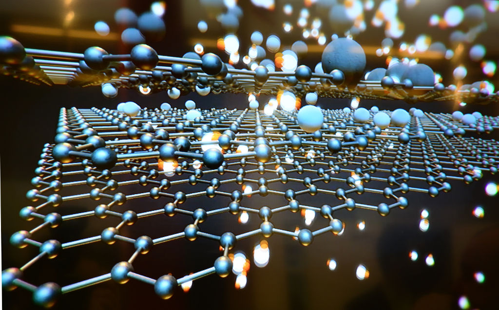
Carbon based EDL capacitor – the confinement effect
There is a great interest for understanding the relationship between the porosity of carbon nano-materials and their specific capacitance.
When electric double-layer formation occurs in a nano-confined micro-environment, the EDL capacitor in porous carbon materials deviates from the classic EDL model on flat interfaces. The degree of the ion solvation under confinement is determined by the pore size in nano-porous materials and by the inter-layer distance in layered materials that is, 2D-layer materials.
Confinement of ions in sub-nanometer pores results in their desolvation, leading to the capacitance increase and deviation from the typical linear behavior on the surface area. During negative polarization of porous carbon materials with the pore sizes <1 nm, a decrease of capacitance is observed. This is due to the ion selection limiting ion transport.
These insights are important for effectively tailoring carbon pore structures and for increasing their specific capacitance. Since carbon material is not an ideal conductor, it is important to consider its specific electric structure. For graphite materials, the availability of the charge carriers increases during the polarization which leads to increased conductivity.
Unified model of electrochemical charge storage under confinement
Since the electrochemical interface in the most technological application is non-planar, the researchers proposed a detailed evaluation and different concept of electrochemical capacitance on such non-ideal interfaces. The team evaluated electrosorption on 2D surfaces and 3D porous carbon surfaces with a continuous reduction in pore size in a step-by-step approach of increasing complexity.
The example provided relates to the charge storage characteristics of lithium ions (Li+) in the graphene sheets of organic lithium-containing electrolytes depending on the number of graphene layers. In a single graphene layer, the capacitive response is potential independent due to the absence of specific adsorption. However, with an increase of graphene sheets, redox peaks emerged that are associated with the intercalation of desolvated lithium ions. Lithium intercalation is responsible for battery wear. The team’s hypothesis was that the transition of solvated lithium ion adsorption on a single graphene sheet into subsequent intercalation of desolvated lithium ions occurs with a continuous charge storage behavior. There can be a seamless transition based on the increased charge transfer between an electrolyte ion and host associated with the extent of desolvation and confinement.
In the presented research, a unified approach was proposed that involves the continuous transition between double-layer capacitance and Faradaic intercalation under confinement. This approach excludes the traditional “single” view of electrochemical charge storage in nano-materials regarded as purely electrostatic or purely Faradaic phenomenon.
The increasing degree of ion confinement is followed by decreasing degree of ion solvation thus the increase ion-host intercalation. This results in a continuum from EDL formation through transitioning state to Faradaic intercalation, typical for EDLC nanomaterial.
Hydrogen (H2) is a lightweight alternative fuel with a high energy density. However, its environmental impact and life cycle efficiency are determined by how it is produced. Today, the main processes of hydrogen production is either by coal gasification or steam reforming of natural gas where in the last step the produced carbon dioxide (CO2) is produced. Usually, this CO2 is released to the environment. The hydrogen produced by these processes lead is called black/brown or grey hydrogen. To improve its carbon footprint, CO2 capture is necessary. This hydrogen is then call blue hydrogen. However, to obtain zero-emission green hydrogen, electrolysis of water using renewable energy is necessary. During the electrolysis process, hydrogen and oxygen are produced on two electrodes (download our more about hydrogen production and utilization as fuel can be found in our latest DIY FC manual).
Climate-related economic pressure for more efficient gas separation processes
The produced hydrogen is not pure in any of the mentioned instances. For example, using steam methane reforming reaction there are many byproduct gases like carbon monoxide, CO2, water, nitrogen and methane gas.
Typically, the CO2 of hydrogen gas is up to 50% contributing to the greenhouse effect caused by burning fossil fuels. Currently, around 80% of CO2 emissions come from fossil fuels. It has been predicted that the concentration of CO2 in the atmosphere will increase up to 570 ppm in 2,100 which increases the global temperature of about 1.9°C.
The traditional processes of gas separation such as cryogenic distillation and pressure swing adsorption have certain disadvantages, for example high energy consumption. Therefore, developing high-quality and low-cost technologies for gas separation is an important intermediate step to produce cheap hydrogen while reducing CO2 emissions.
Application of 2D material towards gas separation
Finding low cost alternatives like membrane-based separation methods for hydrogen-CO2 separation is a potentially lucrative research and it is therefor not surprising that numerous publications have investigated the matter. The various membrane materials for gas separation range from polymeric membranes, nano-porous materials, metal–organic frameworks and zeolite membranes. The goal is to reach a good balance between selectivity and permeance of gas separation. Both are key parameters for hydrogen purification and CO2 capture processes.
A study published the journal Nature Energy by researchers of the National Institutes of Japan, offered a material platform as advanced solution for the separation of hydrogen from humid gas mixtures, such as those generated by fossil fuel sources or water electrolysis. The authors showed that the incorporation of positively charged nanodiamonds into graphene oxide (GO/ND+) results in humidity repelling and high performance membranes. The performance of the GO/ND+ laminates excels particularly in hydrogen separation compared with traditional membrane materials.
Strategy and performance of new membrane materials
Graphene oxide laminates are considered as step-change materials for hydrogen-CO2 separation as ultra permeable (triple-digit permeance) and ultra-selective membranes. Still, graphene oxide films lose their attractive separation properties and stability in humid conditions.
After lamination, graphene oxide sheets have an overall negative charge and can be disintegrated due to the electrostatic repulsion if exposed to water. The strategy to overcome this obstacle was based on the charge compensation principle. That is, the authors incorporated positively and negatively charged fillers as stabilizing agents, and tested different loadings as well as graphene oxide flake sizes. So-prepared membranes were tested for stability in dry and humid conditions while separating either hydrogen from CO2 or oxygen.
The GO/ND+ composite membranes retained up to 90% of their hydrogen selectivity against CO2 exposure to several cycles and under aggressive humidity test. A GO30ND+ membrane with 30% positively charged nano-diamond particles exhibited exceptional hydrogen permeance with more than 3,700 gas permeatin units (GPU) and high hydrogen-CO2 selectivity. Interestingly, incorporation of negatively charged nano-diamond particles had no stabilizing effect. The researcher attributed this mostly to the generation of macro scale voids in ND− systems resulting in the loss of selectivity. This phenomenon is commonly observed in polymer-based nano-composite membranes with poor interfacial interactions
The gas separation properties of the composite membranes were also investigated using an equimolar hydrogen-CO2 feed mixture. The hydrogen permeance decreased by 6% and hydrogen-CO2 selectivity of the GO30ND+ membrane by 13%.
The stability test of the membranes exposure to wet and dry feeds of the equimolar hydrogen-CO2 mixture and hydrogen-oxygen mixture showed that GO/ND+ membranes were reversible membrane properties. On the other hand, graphene oxide-only membranes could not survive a single complete cycle exposure, becoming fully permeable to both gases. The researchers explained that the advantages of GO/ND+ membranes over graphene oxide-only membranes were caused by changes of the pore architecture such as dimensions and tortuosity, which could be improved by optimizing the nano-diamond loading. This results in better permeability without any notable loss of selectivity.
X-ray diffraction analysis showed that the incorporation of nanodiamonds has two major effects on the membrane microstructure: increasing the overall pore volume and reducing the average lateral size. Both make the membrane structure more accessible for molecular transport.
Nevertheless, this relatively new class of humid-resistant membranes still needs more optimization to compete with current industrial separation processes.
Catalysts for low-temperature fuel cells are permanently improved to overcome high costs. Only when low-temperature fuel cells are competitive with internal combustion engines will they be an alternative power source for transportation or even portable devices. The US Department of Energy’s (DOE) milestones for the cost of a light-duty vehicle fuel cell system is $30 per kWnet. However current costs of a proton-exchange membrane (PEM) fuel cells ranges between $45 and $51 kWnet.
Challenged to reduce fuel cell production cost, researchers have suggested changing the fuel cell operating environment from acidic pH to alkaline. This will require to replace PEM by anion-exchange membranes (AEM) in fuel cells. The true advantage of AEM over PEM fuel cells is the cost reduction through cheaper membranes. Additionally, a broader spectrum of materials could be used and the oxygen reduction reaction (ORR) kinetics would be improved. Yet, acidic conditions corrode non-precious metals quickly while at the same time the high loading of platinum group metals (PGM) catalysts need to be reduced as well.
Synthesis of Fe-N-C electrocatalyst and it structure
Researchers from the University of South Carolina, Columbia (USA) together with their partners recently reported in Nature Energy the remarkable performance of inexpensive Fe-N-C cathode catalysts with single-atom Fe-Nx active sites in AEM fuel cell. The Fe-N-C catalyst was constructed in respect to two important aspects: increase the average pore size (ranging from 5-40 nm, 1 µm) as well as the level of graphitization. Both measures reduce the hydrophobicity of the catalyst layer. To optimize their catalyst’s performance, the researchers went through an iterative process using various material characterization techniques. Energy Dispersive Spectroscopy mapping was used to ensure the catalyst composition was homogeneous. Iron atoms in the catalyst were present as single atoms, which was confirmed by Scanning Transmission Electron Microscopy imaging.
Catalyst performance and integration in AEM fuel cells
The electrochemical analyses carried out by the scientists showed that their Fe-N-C catalyst achieved high ORR activity via four-electron O2 reduction. In this reduction reaction, oxygen is directly reduced to water without the intermediate hydrogen peroxide step. The yield of hydrogen peroxide as function of potential over the entire experimental range was less than 1% – a good result for a non-precious metal catalyst. The current density of the reaction was of 7 mA / cm2.
The Fe-N-C catalyst was used on the cathode of a hydrogen-oxygen AEM fuel cell. An high peak power density of 2 W / cm2 was reported. This performance is the highest reported value for polymer membrane fuel cells (AEM and PEM) using a non-precious metal catalyst. Especially the 4x lower loading of Fe-N-C catalyst compared with previous reports makes this type of fuel cell economically interesting. Moreover, the electrocatalyst was stable at voltages of 0.6 V for more than 100 hours.
To evaluate feasibility of Fe-N-C cathode for more practical application, the fuel cell was tested in the air flow as cathode oxidant. The achieved current density was 3.6 mA / cm2 at 0.1 V with a peak power density of over 1 W / cm2. These results again show the highest reported values in the literature up to date compared to other hydrogen-air AEM fuel cell.
Fuel cell test target DOE-criteria
The cell configuration simulating more realistic operation was intended to benchmark against the DOE targets and the DOE2022 milestones. Cathodes with 0.6 mg Pt / cm2 and a 1 mg Fe-N-C per cm2 were compared. The paired cell was operated under conditions similar to the DOE-defined protocol: 0.9 V iR-free, cell temperature 80°C and 100 kPa partial pressure of O2 and H2. A steady-state current density reached at 0.9 V (iR-free) was approx. 100 mA / cm2. This was more than twice the DOE target.
Finally, the next configuration was designed using the DOE2022 milestones protocol postulating that the total precious metal loading should be less than 0.2 mg Pt / cm2. This was achieved by integrating Fe-N-C cathode with low-loading PtRu/C anodes (0.125 mg PtRu per cm2). This cell reached a peak power density of 1.3 W / cm2 under hydrogen-oxygen operation. Recalculating this value to a specific power output of 16 W per mg Pt results in the highest value of any AEM fuel cell ever reported in the literature.
It has been demonstrated that the Fe-N-C electrocatalyst can compete with noble metal-based catalysts for AEM fuel cells. The reported cell configuration provided remarkable performance in terms of activity and durability under fuel cell condition.
Methodology and electrode preparation
Rotating ring disc system – RRDE, was used for evaluation of electrochemical performance for ORR of Fe-N-C catalyst.
Fe-N-C catalyst was prepared with higher density of Fe-Nx centers since it has been reported that a higher carbon proportion also results in a higher number of positions in the graphene sheets available for insertion of active sites.
In the electrochemical cell the electrodes were: working electrode – catalyst was cast on the GC disk and stabilized with 5% Nafion® ;
Platinum mesh was used as counter electrode and Ag/AgCl as reference electrode, 0.1 M KOH was used as electrolyte.
For the tests in anion-exchange membrane fuel cell, gas diffusion electrodes were used: Anode was prepared with low-loading PtRu/C material (0.125 mg PtRu per cm2, 0.08 mg Pt per cm2), while for the cathode Fe-N-C catalyst was used – both were prepared by spraying catalyst ink onto a gas diffusion layer.
Most of the world’s energy needs are currently served by fossil fuels. The International Energy Agency (IEA) annual projection indicates that the global energy demand will increase twice by 2040, mostly in emerging markets and developing economies.
To meet increasing global energy demands and to replace depleting fossil fuels, policy makers believe that alternative clean and renewable energy sources are the best solution. Such renewable energy sources can be electricity for solar, wind or geothermal energy as well as hydroelectric power. The latter, however, has reached a certain degree of saturation in fully industrialized countries.
While solar and wind energy are available in most places of the world at more or less reasonable cost, their biggest disadvantage is that they are intermittent, difficult to store and transport, and difficult to tank in cars, planes and ships. Converting solar and wind energy in hydrogen gas could be an elegant way out of this dilemma as the fuel’s resource can be abundant water. Diversifying the energy mix by adding hydrogen at acceptable cost may prove more efficient with a lower environmental footprint as compared to other fuels. Hence, the interest for water electrolysis and fuel cells is constantly growing.
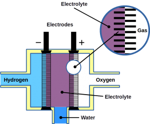
Most of today’s hydrogen is produced through steam reforming of natural gas. However, it can also be made from water electrolysis. Electrolysis is two-electrode reactions: the hydrogen evolution reaction (HER) at the cathode and the oxygen evolution reaction (OER) at the anode.
Fuel cells reverse the reaction and harvest electricity produced by fusing the hydrogen and oxygen atoms back together to obtain water. While there are different types of fuel cells, those commonly used with hydrogen as fuel are polymer electrolyte membrane fuel cells, or PEMFC. The PEM acronym is also often used for proton exchange membranes, which can be made of polymers, for example Nafion™. In PEMFC, energy is liberated through the hydrogen oxidation reaction (HOR) at the anode and oxygen reduction reaction (ORR) at the cathode. To become economically feasible, there are still technical challenges of water electrolyzers and fuel cells to overcome. Some technical problems result in serious system degradation.
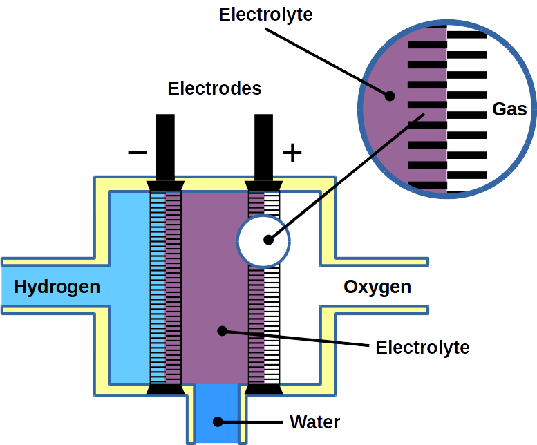
Water is pumped into a fuel cell where two electrodes split it into hydrogen (H2) and oxygen (O2)
A study published in Nature Communications by researcher of Technical University Berlin and the Korea Institute of Science and Technology, suggests using a novel iridium electrocatalyst with multifunctional properties and remarkable reversibility. While iridium also is precious and one of the platinum group metals, the novel Ir-catalyst was designed for the processes where electrochemical reactions change rapidly, such as the voltage reversal of water electrolysis and PEMFC systems. This would integrate the two energy conversion systems in one and therefore be a great economical benefit over existing solutions.
Challenges
Unexpectedly changing operating conditions such as a sudden shut-down of water electrolysis result in increased hydrogen electrode potentials which lead to degradation hydrogen producing electrodes.
In fuel cells, fuel starvation can occur at the anode, leading to voltage reversal. Ultimately, this causes degradation of fuel cell components such as the catalyst support, gas diffusion layer and flow field plates. It has been proposed to introduce a water oxidation catalyst to the anode of the PEMFcs in order to promote OER since it is the reaction that competes with the carbon corrosion reaction.
Design of a unique iridium-based multifunctional catalyst
For the study, a crystalline multifunctional iridium nanocatalyst has been designed considering the mentioned challenges in water electrolysis and fuel cell operation.
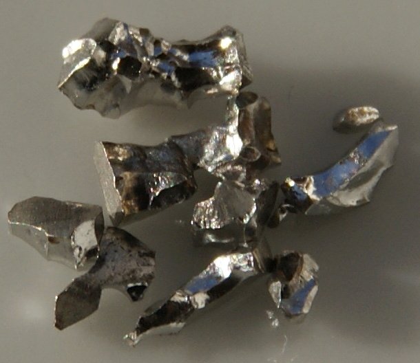
The reason why an iridium-based material has been selected is its remarkable OER activity as well as good HER and HOR catalytic activity. It is a superior material for anodes and cathodes in electrolyzers and for anodes of PEMFC. For comparisons, the researchers synthesized two catalysts using the modified impregnation method: carbon-supported IrNi alloy nanoparticles with high crystallinity (IrNi/C-HT) and with low crystallinity (IrNi/C-LT).
The findings indicated that the surface of IrNi/C-HT had reversibly converted between a metallic character and an oxidic IrNiOx character. Under OER operation that is, anodic water oxidation, the crystalline nanoparticles form an atomically-thin IrNiOx layer. This oxide layer reversibly transforms into metallic iridium when returning towards more cathodic potentials. The reversal allows the catalyst to return to its high HER and HOR activity.
The experiments also revealed that the performance of IrNi/C-LT sharply decrease after carrying out the OER. The catalyst degradation was due to the irreversible destruction of the amorphous IrNiOx surface.
In situ/operando X-ray absorption near edge structure (XANES) and depth-resolving X-ray photoelectron spectroscopy (XPS) profiles, suggested that the thin layers of IrNiOx possess an increase in the number of d-band holes during OER, due to which catalyst IrNi/C-HT exhibited excellent OER activity. As expected, under HER conditions, the thin IrNiOx layer was reversibly converted to metallic surface. The mechanistic study of the reversible catalytic activity of the IrNiOx layer has been additionally analyzed by electrochemical flow-cell using inductively coupled plasma-mass spectrometry (ICP-MS). The results demonstrate that the reversible IrNiOx layers come from a dissolution and re-deposition mechanism.
In addition, the performance and catalytic reversibility of synthetized electrocatalysts were used to perform HOR and OER in a real electrochemical device and tested under fuel starvation of the PEMFC. Using voltage reversal, the fuel cell was converted into an electrolyzer.
Fuel starvation experiments were conducted in a single PEM fuel cell built using IrNi/C-HT and IrNi/C-LT as the catalytically active components in the anode catalyst layer. The initial fuel cell performance of IrNi/C-LT and -HT was lower than that of the commercial Pt/C catalyst due to the lower HOR and metal composition.
Further results demonstrate that IrNi/C-HT catalyst retained its bifunctional catalytic activity, reversibing between HER and OER in a real device. This approach promoted the reversibility of nanocatalysts, which enable a variety of electrochemical reactions and can be used as catalysts to resist the reverse voltage in fuel cells and water electrolysis systems.
At Frontis Energy, we are looking forward to adding the novel iridium catalyst to our Fuel Cell Shop as soon as it becomes available.
Zinc-air batteries are a promising alternative to expensive lithium-ion batteries. Compared with lithium-ion technology, zinc-air batteries have a greater energy density, very low production cost, and superior safety. However, their fundamental inability to recharge has lowered their wide-scale adoption.
Zinc-air batteries use charged zinc particles to store large amounts of electricity at a time. When electricity is required, the charged zinc is combined with oxygen from the air (and water), releasing the stored electricity and producing zincate. This process is known as oxygen reduction reaction (ORR).
Theoretically, this zincate can again be broken down into oxygen and zinc ions by passing electricity through it. This process, in turn, is called oxygen evolution reaction (OER). Using these reactions, zinc-air batteries can be made rechargeable, competing with lithium-ion batteries.
The major challenge of the recharging process is the sluggish kinetics of the reactions which lead to poor cycle life. These batteries require a catalyst that could potentially enhance the ORR and the OER reactions, making their kinetics fast. Hence, the development of highly efficient catalysts is of paramount importance for rechargeable zinc-air batteries.
Previous studies have suggested transition-metal oxides as great bifunctional ORR / OER catalysts because of their ability to provide sites for the reversible adsorption of oxygen. But the methods involved in creating well-defined defects for reversible adsorption of oxygen in such oxides are challenging.
To investigate the use of cobalt(II) oxide nanosheets deposited on stainless steel or carbon cloth as a bifunctional catalyst, a group of researchers from different universities of China and Canada collaborated and conducted several experiments. Their research findings were published in the journal Nano Energy .
Research approach
Preparation of catalyst
Different nano-structures were prepared using simple heat treatment and electrodeposition to test them as bifunctional electrocatalysts. The type of nano-structures prepared were:
Cobalt hydroxide nanosheets on steel and carbon cloth
Layered cobalt (II) oxide nanosheet on steel and carbon cloth
Cobalt (II) oxide on steel
Layered cobalt tetroxide nanosheet on steel
Material Characterization
To understand the characteristics of the prepared samples, various analyticaland tests were carried out:
Study of surface chemistry using atomic force microscopy and other equipment. To draw correlations between the oxygen vacancy defects and intrinsic ORR / OER activity linear sweep voltammogram of the samples were investigated in a three-electrode electrochemical cell.
Charging and discharging tests
Later discharge and charge cycling tests of single cells were operated by the battery testing system.
Results
The simple heat treatment strategy created oxygen vacancy sites. According to the authors, layered cobalt-oxide nano-sheets exhibited excellent bifunctional ORR / OER performance. Investigations suggested abundant oxygen vacancies and cobalt sites be the reason for enhanced ORR / OER performance. Later, the developed layered cobalt-oxide nanosheets on steel were used as an electrode in a rechargeable zinc-air flow battery and a record-breaking cycle life of over 1,000 hours with nearly unchanged voltage was observed. Galvanostatic discharging-charging cycles also demonstrated long life and high energy efficiency.
This research carried out provides a new method to design highly efficient bifunctional ORR / OER catalysts that could be used to enhance the cycle life of rechargeable zinc-air flow batteries. At Frontis Energy we are looking forward to industrial applications.
(Photo: Engineersforum)
Reference: https://doi.org/10.1016/j.nanoen.2020.105409 Wu et al., Cobalt (II) oxide nanosheets with rich oxygen vacancies as highly efficient bifunctional catalysts for ultra-stable rechargeable Zn-air flow battery, 2021
The demand for energy is increasing and raw material for the fossil fuel economy is diminishing. Moreover, the emission of gases from fossil fuel usage significantly degrades air quality. The carbon by-products produced from these fossil fuels severely affect the climate.
Hence, there is a need to find a renewable energy resource, that can be produced, stored, and used easily as per requirement. Hydrogen can be a promising energy resource as it is an abundantly available, non-toxic resource, and can be readily used to store excess electrical energy.
Hydrogen when combined with oxygen in a fuel cell produces electricity and the by-products obtained are water and heat. Based on the method of production of hydrogen it is categorized as blue hydrogen and green hydrogen. Blue hydrogen is produced from fossil fuels such as methane, gasoline, coal while green hydrogen is produced from non-fossil fuels / water. The cleanest way to produce eco-friendly hydrogen is via electrolysis of water where water is electrolyzed to separate hydrogen and oxygen. Renewable energy can be used as a power electrolyzer to produce hydrogen from water. Solar driven photo electrochemical (PEC) water splitting is one of the common method used these days. In photo electrochemical (PEC) water splitting, hydrogen is produced from water using sunlight.
PEC cells comprise of a working photoelectrode and a counter electrode. The photoelectrode consists of semiconductor material with a band gap to absorb solar light and generate an electron-hole pair. The photo-generated charges are responsible for the oxidation of water and its reduction into hydrogen. The PEC suffer devices from low stability and efficiency.
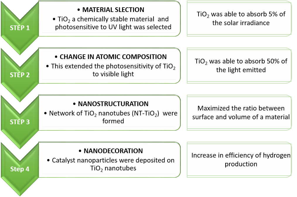
A comparative study between cobalt and nickel oxide nanoparticles deposited onto TiO 2 nanotubes prepared through anodization was carried out. The TiO 2 nanotubes were decorated with CoO (cobalt oxide) and NiO (nickel oxide) nanoparticles using the reactive pulsed laser deposition method. The surface loadings of CoO or NiO nanoparticles were controlled by the number of laser ablation pulses. The efficiency of CoO and NiO nanoparticles as co-catalysts for photo-electrochemical water splitting was studied by cyclic voltammetry, under both simulated sunlight and visible light illuminations and by external quantum efficiency measurements
The entire research work was carried out in the following steps:
Steps followed to improve the efficiency of hydrogen production
In this study Cobalt (CoO) and Nickel (NiO) oxides were considered as effective co-catalysts for splitting water molecules. Both co-catalysts improved photo-electrochemical conversion of ultra violet as well visible light photons.
However, CoO nanoparticles were found to be the best co-catalyst under visible light illumination, with a Photo Conversion Efficiency almost 10 times higher than for TiO 2 . The performance of CoO nanoparticles got enhanced in the visible spectral region (λ> 400 nm). The possible reason can be a consequence of their visible bandgap which enables them to harvest more photon in the 400-500 nm range and transferring effectively the photo-generated electrons to TiO 2 nanotubes.
At Frontis Energy we are exited about these new discovery to improve hydrogen production from sunlight and hope to see an industrial application soon.
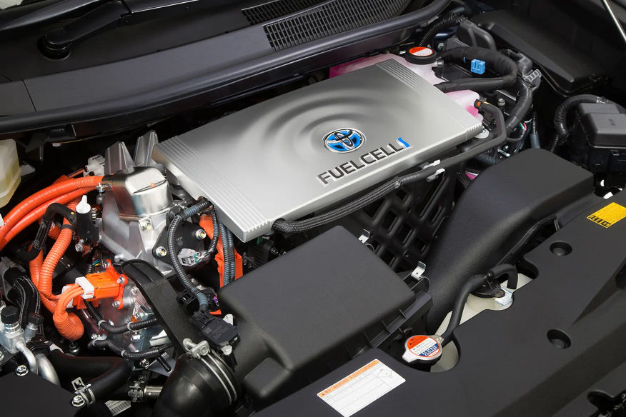
Energy-converting devices such as fuel cells are among the most efficient and clean alternative energy-producing sources. They have the potential to replace fossil-fuel-based power generators. More specifically, proton exchange membrane fuel cells (PEMFCs) are promising energy conversion devices for residential, transportation and portable applications owing to their high power density and efficiency at low operating temperatures (ca. 60–80 °C). For the complete approach, with electrolytic hydrogen renewable sources, PEM fuel cells can become one of the cleanest energy carriers. This is because water is the final product of such energy conversion systems. Currently, Nafion™ membranes are regularly used as hydrogen barriers in these fuel cells.
A Proton exchange membrane
Sufficient hydrogen gas supply is crucial for practical application of the PEMFC systems. Currently, expensive high-pressure tanks (70 MPa) are state-of-the-art for hydrogen storage. Besides cost, there are other drawbacks such as portability and safety. In order to address these issues, alternative hydrogen storage materials have been extensively investigated. For example, metal hydrides and organic hydride materials, can fix and release hydrogen via covalent bonding.
Now, Dr. Junpei Miyake and colleagues of the University of Yamanashi, Japan, have proposed an “all-polymer” rechargeable PEMFC system (RCFC). The work has been published in Nature Communications Chemistry. Their strategy was to apply a hydrogen-storage polymer (HSP) sheet (a solid-state organic hydride) as a hydrogen-storage medium inside the fuel cell. With this approach, the issues like toxicity, flammability and volatility as well as concerns related to other components such as the fuel reservoir, feed pump and vaporizer were solved. The HSP structure is based on fluorenol/fluorenone groups that take over hydrogen-storage functionality.
In order to test the performance of their HSP-based rechargeable fuel cell, the scientists attached the HSP sheet of the membrane electrode to the catalyst layer of the anode. At the same time, the cathode side was operated as in a regular PEMFC. The researchers reported that an iridium catalyst has been applied to the inside of the HSP sheet to improve the hydrogen-releasing and fixing processes.
Fuel cell operation, cycle performance and durability were tested using cycles of 6 periodic steps. At first, hydrogen was infused into HSP sheet for 2 h, followed by nitrogen gas flushing to remove hydrogen from the anode. Then, heating of the cell up to 80°C to initiated hydrogen release from the HSP sheet. Together with oxygen gas supplied to the cathode side the fuel cell produced constant electrical current.
The team demonstrated that their HSP sheet released 20%, 33%, 51%, or 96% of the total fixed hydrogen gas in 20, 30, 60, or 360 min, respectively. The temperature was 80°C in the presence of the iridium catalyst. Also, the iridium catalyst could absorb up to 58 mol% hydrogen, which was considerably lower than that stored in the HSP. The maximum operation time was approximately 10.2 s / mgHSP (ca. 509 s for 50 mg of HSP) at a constant current density of 1 mA / cm2. The RCFCs reached cycleability of least 50 cycles. In addition, the utilization of a gas impermeable sulfonated poly-phenylene membrane (SPP-QP, another type of PEM) turned out to be a good strategy to enhance the opration time of the RCFC.
The advantageous features of the reported RCFC system include better safety, easier handling and lower weight. These are perfect for example in mobile application such as fuel cell vehicles. However, for the improvement of the RCFC performance, hydrogen storage capacity and kinetics (H2-releasing/fixing reactions) as well as catalyst stability need further improvements.
Life cycle analyzes of vehicles with different drive concepts are the subject of many studies. When it comes to CO2 emissions, the energy source is crucial. Two main developments are discussed today: the electrification of the propulsion system (i.e. fully and partially electrified vehicles) and the electrification of fuels (i.e. hydrogen and synthetic fuels).
In the manufacture of synthetic fuels, water is broken down into oxygen and hydrogen by electrolysis with renewable electricity. Due to the temporary oversupply of renewable electricity, this energy is particularly cheap. The hydrogen can then be used in hydrogen vehicles propelled by fuel cells. Alternatively, CO2 can be converted into hydrocarbons with hydrogen and then used in conventional combustion engines in a climate-neutral manner. The advantage of fuel cell vehicles is their high efficiency and the low cost of electrolysis. The disadvantage is the lack of a hydrogen infrastructure. Converting from hydrocarbons to hydrogen would cost trillions. The cheaper alternative would be synthetic hydrocarbons. However, the development is still in its infancy and the production of synthetic fuels cannot yet be carried out on a large scale.
Hydrogen and synthetic fuels are a necessary addition to electromobility, especially for long-distance and load transport. The widespread view that the low level of efficiency of internal combustion engines makes these fuels uninteresting ignores the possibility of using them to store and transport energy and to enable climate neutrality for air and shipping traffic. If you compare the CO2 emissions from electric motors and electrified fuels, it becomes clear that these mainly depend on the CO2 pollution of the electricity used.
Synthetic fuel sources
The production of synthetic fuel requires renewable electricity, water and CO2. The technical processes are known. However, the first large-scale industrial plants are only in the planning phase. However, pilot projects such as that of the Canadian company Carbon Engineering have shown the technical feasibility of scaling. The generation costs depend mainly on the size of the plant and the electricity price, which results from the local conditions, the structure of the electricity market and the share of renewable electricity.
The decentralized production of these fuels brings not only climate neutrality but also geopolitical gains. Since CO2 and renewable energy – in contrast to lithium – are generally accessible resources, users of this technology become independent of energy imports. At Frontis Energy we think these are strong arguments in favor of synthetic fuels.
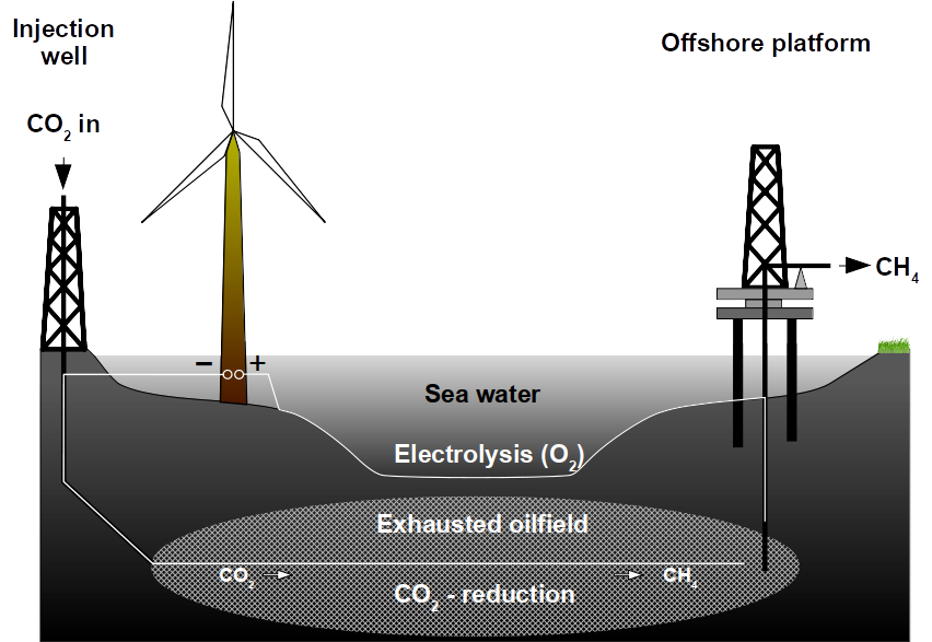
An abandoned or unproductive oilfield can be reused for methane production from CO2 using renewable electrical power. Exhausted oilfields can be reactors for the conversion of renewable energy to natural gas using microbes. To achieve this, an oilfield can be made electrically conductive and catalytically active to produce natural gas from renewable power sources. The use of natural gas is superior to any battery because of the existing infrastructure, the use in combustion engines, the high energy density and because it can be recycled from CO2. Oilfields are superior to any on-ground production because of the enormous storage capacities. They are already well explored and these geological formations underwent environmental risk assessments. Lastly, the microbial power-to-gas technology is already available.
Process summary
Whole process (end-to-end via methane)
50% electrical efficiency
Energy density of methane
180 kWh kg−1
Storage capacity per oilfield
3 GWh day−1
Charge/Discharge cycles
Unlimited
Investment (electrodes, for high densities)
$51,000 MW−1
Cost per kWh (>5,000 hours anode lifetime)
<$0.01 kWh−1
Electrolyte
Seawater
The Problem
To address the problem of storing renewable energy, batteries have been proposed as a possible solution. Lithium ion batteries have a maximum energy storage capacity of 0.3 kWh kg−1. To date, this is considered the best trade-off between cost and efficiency but these batteries are still too inefficient to replace gasoline, which has a capacity of about 13 kWh kg−1. This makes battery driven cars heavier than conventional cars. Lithium air batteries are considered a possible alternative because they can reach theoretical capacities of 12 kWh kg−1 but technical difficulties have prevented them from being used for transportation.
In contrast, methane has an energy density of 52 MJ kg−1 corresponding to 180 kWh kg−1 which is second only to hydrogen with 500 kWh kg−1, not counting in nuclear energy. This high energy density of methane and other hydrocarbons along with their facile usage, is the reason why they are used in combustion and jet engines that drive nearly all transportation to date. While electrical cars seem to be a tempting green alternative, the fact that combustion engines and the fueling infrastructure are so wide-spread makes it difficult to switch.
In addition to the difficulty of changing habits, battery-driven electrical cars need other limited natural resources such as lithium. To equip all 94 million automobiles produced worldwide in 2017, 3 mega tons lithium carbonate would need to be mined annually. This is nearly 10% of the entire recoverable lithium resources of 35 mega tons worldwide. Although lithium and other metals can be recycled, it is clear that metal based batteries alone will not build the bridge between green energy and traditional ways of transportation due to the low energy densities of metals. And this does not even take into account other energy demands such as industrial nitrogen fixation, aviation or heating.
For Germany, with its high proportion of renewable energy, fuel for cars is not the only problem. As renewable energy is generated in the north, but many energy consumers are in the south, the grid capacity is frequently reached during peak production hours. A steadier energy output can only be accomplished by decentralizing the production or by energy storage. To decentralize production, homeowners were encouraged to equip their property with solar panels or windmills. As tax incentives phase out, homeowners face the problem of energy storage. The best product for this group of customers so far are again lithium ion batteries but investment costs of $0.10 kWh−1 are still unattractive especially because these products store the energy as electricity which can only be used for a short time and is less efficient than natural gas when used for heating.
Natural gas is widely used as energy source today and the global energy infrastructure is designed for natural gas and other fossil fuels. Increasing demand and limited resources for these fossil fuels were the main drivers of oil and gas prices during the last years, slowed by the recent economic crises and hydraulic fracturing (fracking). The high oil price attracted investors to recover oil using techniques that become increasingly expensive and are environmental risks such as deep-sea drilling or tar sand extraction. Ironically, the high oil price made costly renewable energies an economically feasible alternative and helped driving down their cost. Since habits are difficult to change and building an entirely new infrastructure only for renewable energies does not seem economically feasible today while CO2 drives global warming, a more realistic solution needs to be found.
Microbial Power-to-Gas could be a bridging technology that integrates renewable energy into the existing fossil fuel infrastructure. It reaches break even in less than 2 years if certain preconditions are met. This is accomplished by integrating methane produced from renewable energy into the current oil and gas producing infrastructure. The principal idea is to use carbon instead of metals as energy carrier because of its high energy density when bound to hydrogen. The benefits are:
High energy density of 180 kWh kg−1 methane
Low investments due to existing infrastructure (natural gas, oilfield equipment)
Carbon is not a limited resource
Low CO2 footprint due to CO2 recycling
Methane is a transportation fuel
Methane is the energy carrier for the Haber-Bosch process
Inexpensive catalysts further reduce initial investments
Low temperatures due to bio-catalysis
No toxic compounds used
No additional environmental burden because existing oilfields are reused
The solution
Methane can be synthesized by microbes or chemically. Naturally, methane is produced by anaerobic (oxygen-free) microbial biomass decomposition. The energy for biomass synthesis is provided by sunlight or chemical energy like hydrogen. In the case of methanogens (methane producing microbes), energy is harvested after CO2 and hydrogen were released from biomass decomposition following a 1-to-4 stoichiometry:
CO2 + 4 H2 → CH4 + 2 H2O
Without microbes, methane is produced by the Nobel-prize winning Sabatier reaction and several attempts are currently underway to use it on industrial scale. It is necessary to split water into hydrogen and use this to reduce CO2 in the gas phase. A major drawback of the Sabatier reaction is the need for high temperatures around 385ºC, and a nickel catalyst that becomes quickly spent. Methanogens use iron-nickel enzymes called hydrogenases to harvest energy from hydrogen, but do so at ambient temperatures.
Power-to-Gas concept for exhausted oilfields. Electrolysis catalyzes water splitting inside the oilfield producing methane gas and O2.
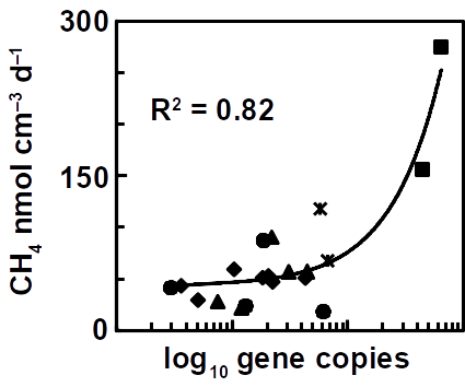
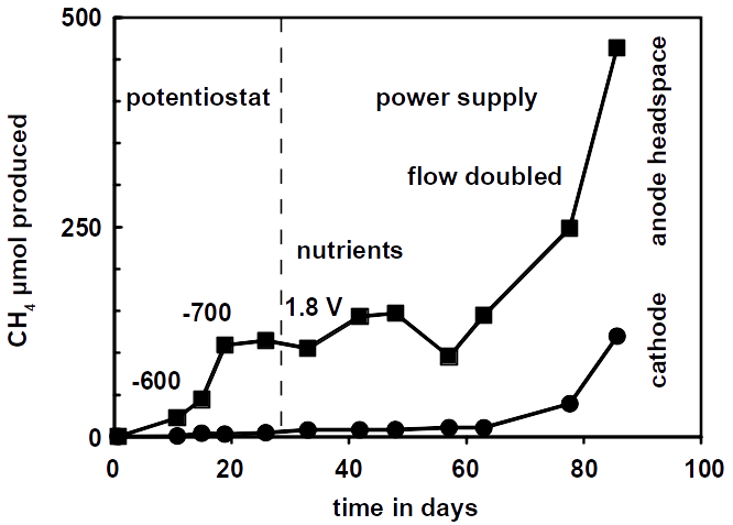
The future challenge will be to accelerate methane production rates as has been reported for a high temperature oilfield cultures. Besides increasing the temperature, the most obvious solution is to use a higher reactive surface and bringing both electrodes closer together. Using carbon brushes that are poor hydrogen catalysts but provide a higher surface for microbial attachment is one possibility. Methane production correlates with microbial cell numbers in the reactors.
The number of methanogens in microbial electrolysis reactors correlates with the electrode surface.
To overcome the problem of expensive carbon (and also steel) brushes for large scale applications,exhausted gas and oilfields could be used. They provide a high surface area and are usually economic liabilities and not assets. Methanogens inhabit oilfields where they carry out the final step in anaerobic petroleum degradation. Hence, oilfields can be seen as bioreactors at geological scale. Geological formations provide ideal conditions for producing, storing and extracting methane.
Open questions and potential solutions
Oilfield porespace volume
The Californian Summerland oilfield, for instance, has been abandoned and extensively studied in the past. It produced 27 billion barrels of oil and 2.8 billion m3 methane during its lifetime of 90 years. This maximum load of 3.5 billion m3 left the same volume of porespace filled with seawater behind. Only 2% of these pores are larger than 50 µm, which is necessary for microbial growth assuming dimensions of 1 x 2 µm of a methanogen cell. Experiments showed that the resulting 70 million m3 accessible porespace have a storage capacity of 35,000 TW. That is a lot of methane assuming a solubility of 0.74 kg methane m−3 seawater at 500 m water depth. All German off-shore windfarms together have a capacity of 7,000 MW. Obviously, the limiting factor is not the volumetric storage capacity of an oilfield.
Microbial methane production rates
But how fast can microbes produce methane in an hypothetical oilfield? Under optimal conditions, methanogens that grow on electrodes (typically the genus Methanobacterium or Methanobrevibacter) can produce methane at a rate of 100-200 nmol ml−1 day−1 (equals 2.24-4.48 ml l−1 day−1) depending on catalyst and potential. Using a production rate of 15 J ml−1 day−1 of methane (190 nmol ml−1 day−1), the entire microbially accessible oilfield (2%) has a capacity of 3.6 million MBtu per year. Microbes would theoretically consume 1 TWh per year for 3.6 million MBtu methane production if there were no losses and electrical power is translated into methane 1-to-1. A power generator of 121 MW would be sufficient to supply the entire oilfield at these rates. However, all German off-shore windfarms produce 7,000 MW meaning that only 3% off-peak power can be captured by our example oilfield. Therefore, the catalytic surface and activity must be increased to accelerate methane conversion rates.
Since methanogens produce methane from hydrogen, not only the 2% porespace big enough for cells can be used resulting in an increased catalytic surface to nearly 60%. A hydrogen catalyst needs to be found that does not out-pace methanogen growth to keep the reservoir pH within the limits of 6-8 required for methanogen growth. This hydrogen catalyst must be cheap and render an oilfield electrically conductive. A chemical formulation that mimics microbial hydrogen catalysis could be used. It has the potential to turn a non-conductive and non-catalytic oilfield into a conductive hydrogen catalyst sufficient to sustain methane production needed to store all of Germany’s electricity produced by off-shore windfarms. This catalyst is soluble in water when inactive. To become active, it coats mineral surfaces by precipitation that can be triggered by indigenous microbes or by electrical polarization. The investment would be $2.3 million per MW storage capacity ($16 billion for the entire 7,000 MW). Due to microbial growth, the catalytic activity of the system improves during operation and there is no need for the second component if an immediate production is not crucial. The investments made on the cathode side would then be as low as $600 per MW ($4.2 million for 7,000 MW).
Anodes
As the cathodic side of the reaction can be excluded as limiting factor, the anode needs to be designed. Several commercially available anodes such as mixed metal oxides (up to 750 A m−2) with platinum on carbon black or niobium anodes (Pt/C, 5-10 kA m−2) could be used. Anodes based on platinum are the most cost-efficient material available on the market. Investments made for Pt/C (10%, 6 mg cm−2) anodes will amount to $50,000 per MW ($350 million for 7,000 MW). However, the exact amount of Pt needed for the reaction still needs to be evaluated in an experiment because the corrosion rate at 2 V cell voltage is unknown. An often cited value for the lifetime of fuel cells is 5,000 hours and is used here to determine the costs per kWh. For 5,000 hours lifetime, the costs per kWh will be at the targeted limit of $0.01 but may be well below that because Pt/C anodes can be recycled and the Pt load may be reduced to 3 mg cm−2 (5%). Alternatively, steel anodes (SS316, 2.5 kA m−2, $54,000 per MW) can be used but it is unclear when steel anodes fail to electrolyze. In conclusion, the anodic side is the cost-driving factor. Hopefully, better water splitting anodes will lower these costs in future.
Cost estimation summary
Windfarms
Already in place
CO2 injection
Already occurred
Natural gas capturing equipment
Already in place
Microbial seed
Wastewater from oil rig
Cathode costs
$600 MW−1
Anode costs
$50,000 MW−1
Electrolyte (seawater)
Free
Total (>5,000 hours anode lifespan)
<$0.01 kWh−1
Energy and conversion efficiencies
The whole cell voltage for microbial power-to-gas reactions varies from 0.6 to 2.0 V, depending on cathodic rates, anodic corrosion and the presence of a membrane. Higher voltages will accelerate anode corrosion, again, making anodes the limiting factor. As the voltage decreases, methane production rates become slower but also more efficient. The voltage also depends on the pH of the oilfield. An oilfield that underwent CO2 injection as enhanced recovery method will have a low pH, providing better conditions for hydrogen production but not for microbial growth and must be neutralized using seawater. As stated above, the oilfield, being the cathode, is not limiting the the system. The use of Pt/C anodes eliminates the overpotential problem on the anode side. Hence, we can assume an ideal system that splits water at 1.23 V. However, the voltage is often 2 V due to anode and cathode overpotentials. Optimized cultures and cathodes produce about 190 nmol ml−1 day−1 methane which equals 0.15 J ml−1 day−1 using the energy of combustion of 0.8 MJ mol−1. The same electrolysis cell consumes 0.2 mW at a cell voltage of 2 V which equals 0.17 J ml−1 day−1 and the resulting energy efficiency is 91%. The anodes can be simple carbon brushes and the two chambers of the cell are separated by a Nafion™ membrane. The system can still be optimized by using Pt/C anodes and by avoiding membranes.
The overall electricity-methane-electricity efficiency also depends on the consumption side efficiency where methane is used in combustion engines and gas fired power plants. Such power plants frequently operate at efficiencies of 40- 60%. Assuming a reasonable power efficiency of 80% (see above), the overall electrical power recovery using gas fired power plants will be up to 50%. Besides the high efficiency of gas fired power plants, they are also easy to build and therefore contribute the a better power grid efficiency. Coal fired power plants can be upgraded to gas fired power plants.
Experimental approach
The conversion efficiencies of charge (Coulombs) transported across the circuit are usually between 70-100% in these systems depending on the electrode material. Another efficiency limitation could arise from mass transport inhibition. Mass transport can be improved by pumping electrolyte adding more costs for pumping which still have to be determined. However, since most oilfields undergo seawater injection for enhanced oil recovery the additional cost may be negligible. The total efficiency has yet to be determined in scale-up experiments and will depend on the factors mentioned above.
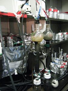
The reactor simulates oilfield conditions using sand as filling material under continuous flow of electrolyte.
Controlling the pH is crucial. Alkaline pHs significantly impede hydrogen production and therefore methanogenesis. This can be addressed by a software that monitors the pH and adjusts the potential accordingly. Addition of acids is not desired as this drives the costs. The software can also act as potentiostat that then fully controls the methane production process. To test the process under more realistic conditions, a drill core from an oilfield must be obtained.
Results show methane production in the simulation reactor. The appearance of methane in the anode compartment was a result of flow from the cathode to the anode, carrying produced methane with it.
Return of investment of the microbial power-to-gas process
The the microbial power-to-gas process in unproductive oilfields is economically superior to all other storage strategies because of the low start-up and operating costs. This is achieved because the major investments are the installation of oil- and gas production equipment and renewable power plants which are already in place as a precondition. These investments break even in a short amount of time.
But how can the microbial Power-to-Gas process accelerate the return of investment in renewable energy? Only 8 out of 28 active off-shore windfarms reported their investment costs. These 8 produce roughly half the overall power of 1,600 MW corresponding to $7 billion. While the maximum production of an oilfield with unlimited supply of electricity would yield hypothetical 3.6 million MBtu natural gas per year resulting a return of $13 million per year the real production is limited by off-peak power generated by renewable energy production. Assuming that the maximum annual methane production corresponds to 10% excess electrical power, $15 million per year can by generated by selling 4.3 million MBtu methane per year on the market. These are $15 million that are not lost during off-peak shutdowns. Clearly, this conservative estimate can help to compensate the investment in renewable energy earlier. It also decreases the investment risk because the investment calculations for new wind farms can be made on a more reliable basis.
In the example using all German windfarms (7,000 MW) this compensation roughly doubles. Using the $60 million generated by methane sales per year, the investment of $4 million for the cathodic catalyst and the $36 million for the Pt/C anodes are compensated for within less than a year. No other investments are required because the target oilfield already produced oil and gas and all necessary installation are in working condition. The target oilfield is swept using seawater as secondary extraction method. Electrical installations are in place for cathodic protection of production equipment in order to prevent microbial corrosion, which, however, may need to be upgraded to pass the now higher power densities. Moreover, CO2 is used from CO2 injection as tertiary enhanced oil recovery method. Only the pH may then need to be adjusted to sustain life by sweeping with seawater.
And this is not the end of oilfield storage capacity. In theory, an oilfield can store the entire amount of renewable energy produced in one year globally, allowing more than enough head room for future development and CO2 sequestration.