Posted on

Remarkable performance of Fe–N–C cathode electrocatalysts in anion-exchange membrane fuel cells (AEMFC)

Catalysts for low-temperature fuel cells are permanently improved to overcome high costs. Only when low-temperature fuel cells are competitive with internal combustion engines will they be an alternative power source for transportation or even portable devices. The US Department of Energy’s (DOE) milestones for the cost of a light-duty vehicle fuel cell system is $30 per kWnet. However current costs of a proton-exchange membrane (PEM) fuel cells ranges between $45 and $51 kWnet.

Challenged to reduce fuel cell production cost, researchers have suggested changing the fuel cell operating environment from acidic pH to alkaline. This will require to replace PEM by anion-exchange membranes (AEM) in fuel cells. The true advantage of AEM over PEM fuel cells is the cost reduction through cheaper membranes. Additionally, a broader spectrum of materials could be used and the oxygen reduction reaction (ORR) kinetics would be improved. Yet, acidic conditions corrode non-precious metals quickly while at the same time the high loading of platinum group metals (PGM) catalysts  need to be reduced as well.

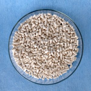
Synthesis of Fe-N-C electrocatalyst and it structure

Researchers from the University of South Carolina, Columbia (USA) together with their partners recently reported in Nature Energy the remarkable performance of inexpensive Fe-N-C cathode catalysts with single-atom Fe-Nx active sites in AEM fuel cell. The Fe-N-C catalyst was constructed in respect to two important aspects: increase the average pore size (ranging from 5-40 nm, 1 µm) as well as the level of graphitization. Both measures reduce the hydrophobicity of the catalyst layer. To optimize their catalyst’s performance, the researchers went through an iterative process using various material characterization techniques. Energy Dispersive Spectroscopy mapping was used to ensure the catalyst composition was homogeneous. Iron atoms in the catalyst were present as single atoms, which was confirmed by Scanning Transmission Electron Microscopy imaging.

Catalyst performance and integration in AEM fuel cells

The electrochemical analyses carried out by the scientists showed that their Fe-N-C catalyst achieved high ORR activity via four-electron O2 reduction. In this reduction reaction, oxygen is directly reduced to water without the intermediate hydrogen peroxide step. The yield of hydrogen peroxide as function of potential over the entire experimental range was less than 1% – a good result for a non-precious metal catalyst. The current density of the reaction was of 7 mA / cm2.

The Fe-N-C catalyst was used on the cathode of a hydrogen-oxygen AEM fuel cell. An high peak power density of 2 W / cm2 was reported. This performance is the highest reported value for polymer membrane fuel cells (AEM and PEM) using a non-precious metal catalyst. Especially the 4x lower loading of Fe-N-C catalyst compared with previous reports makes this type of fuel cell economically interesting. Moreover, the electrocatalyst was stable at voltages of 0.6 V for more than 100 hours.

To evaluate feasibility of Fe-N-C cathode for more practical application, the fuel cell was tested in the air flow as cathode oxidant. The achieved current density was 3.6 mA / cm2 at 0.1 V with a peak power density of over 1 W / cm2. These results again show the highest reported values in the literature up to date compared to other hydrogen-air AEM fuel cell.

Fuel cell test target DOE-criteria

The cell configuration simulating more realistic operation was intended to benchmark against the DOE targets and the DOE2022 milestones. Cathodes with 0.6 mg Pt / cm2 and a 1 mg Fe-N-C per cm2 were compared. The paired cell was operated under conditions similar to the DOE-defined protocol: 0.9 V iR-free, cell temperature 80°C and 100 kPa partial pressure of O2 and H2. A steady-state current density reached at 0.9 V (iR-free) was approx. 100 mA / cm2. This was more than twice the DOE target.

Finally, the next configuration was designed using the DOE2022 milestones protocol postulating that the total precious metal loading should be less than 0.2 mg Pt / cm2. This was achieved by integrating Fe-N-C cathode with low-loading PtRu/C anodes (0.125 mg PtRu per cm2). This cell reached a peak power density of 1.3 W / cm2 under hydrogen-oxygen operation. Recalculating this value to a specific power output of 16 W per mg Pt results in the highest value of any AEM fuel cell ever reported in the literature.

It has been demonstrated that the Fe-N-C electrocatalyst can compete with noble metal-based catalysts for AEM fuel cells. The reported cell configuration provided remarkable performance in terms of activity and durability under fuel cell condition.

Methodology and electrode preparation

  • Rotating ring disc system – RRDE, was used for evaluation of electrochemical performance for ORR of Fe-N-C catalyst.
  • Fe-N-C catalyst was prepared with higher density of Fe-Nx centers since it has been reported that a higher carbon proportion also results in a higher number of positions in the graphene sheets available for insertion of active sites.
  • For the comparison Pt/C electrode was analyzed.
  • In the electrochemical cell the electrodes were: working electrode – catalyst was cast on the GC disk and stabilized with 5% Nafion® ;
  • Platinum mesh was used as counter electrode and Ag/AgCl as reference electrode, 0.1 M KOH was used as electrolyte.
  • For the tests in anion-exchange membrane fuel cell, gas diffusion electrodes were used: Anode was prepared with low-loading PtRu/C material (0.125 mg PtRu per cm2, 0.08 mg Pt per cm2), while for the cathode Fe-N-C catalyst was used – both were prepared by spraying catalyst ink onto a gas diffusion layer.

Image: iStock

Posted on

Smart fuel cells catalyzed by self-adjusting anodes improve water management

Hydrogen fuel cells are often regarded as a key element in the green energy transition. Their efficiency is double the thermochemical energy conversion of internal combustion engines. Hydrogen fuel cells convert the chemical energy of hydrogen and oxygen directly into electricity and water. Hence, water plays a central role in fuel cells. It supports ion transport and participates is product of the reaction itself. In an anion exchange membrane fuel cell (AEMFC), for the oxygen reduction reaction to take place, the water in the anode catalyst layer (ACL) must diffuse to the cathode catalyst layer (CCL). In summary, water management is required to remove water from the ACL for higher efficiency of hydrogen diffusion and to balance the water in the entire membrane electrode assembly (MEA).

Significant research efforts have been made to achieve conditions that is suitable for both the anode and cathode in AEMFC. Asymmetric humidification of reactant gases was proposed to be beneficial to achieve well equilibrated water balance between the two electrodes. At higher temperatures, excess anode water evaporates. It also causes deficiencies at the cathode which also requires water to function. To counteract this, a new system that controls the back pressure at the anode and cathode was introduced. However, external control mechanisms (active control) increase the complexity of the system control.

This is where a passive control system involving MEA modification comes into the picture. Moisture control in a fuel cells can be achieved by designing a suitable gas diffusion layer. Adopting different types of hydrophobic materials for the anode and hydrophilic for the cathode can improve overall fuel cell performance. Poly ethylene tetrafluoroethylene (PTFE) copolymer ion exchange membranes, such as Nafion™ have high water mobility. This property can help water back diffusion to avoid anode flooding while preventing dehydration of the cathode. Designing a gradient microstructure or ionomer content within the CCL could also be useful to improve cell performance and durability.

Recent research published in the journal Cell Reports Physical Science addresses these questions. The presented study was carried out to assess a multi-layer CCL design with the gradient capillary force which has a driving effect on water to solve the water balance problem of anodes in AEMFC. For the purpose of the study, platinum on carbon and platinum-ruthenium on carbon were selected as anode catalysts. Ruthenium increases the hydrogen oxidation reaction activity and possesses beneficial structural properties. Water management and performance of AEMFC would be influenced by the structure of the ACL.

Microstructure analysis of ACLs

ACLs composed of different layers of Pt/C and PtRu/C and a mixed version with a similar thickness of around 9-10 µm were analyzed with energy-dispersive X-ray spectroscopy (EDX).

Pt/C ACL had pores of less than 150 nm while PtRu/C catalysts pores ranged between 300-400 nm. The mixed ACL had a pore size <200 nm.

The researchers concluded that Pt/C and PtRu/C ACL had a stratified and gradient pore size distribution spanning across the anion exchange membrane and the gas diffusion layer. The mixed ACL, however, had a homogenous pore structure throughout the MEA.

Membrane electrode assembly using a polymer electrolyte membrane

Moisture adsorption and desorption behavior of ACLs

To investigate moisture adsorption and desorption, the change of the fuel cell’s moisture content was checked with regards to different levels of relative humidity.

It was observed that the moisture content level increased by up to 50% mass weight along with an increase in relative humidity from 20% to 80%.

With an extended equilibrium time for a relative humidity of 80%, the moisture content of Pt/PtRu and PtRu/Pt ACL began to decrease. This was evidence for the self-adjusting water management behavior.

Desorption at a relative humidity of 60% was done. The water content in ACL showed rapid adsorption and slow-release properties at each relative humidity setting.

Physical adjustment of water behavior was observed in PtRu/Pt ACLs. This was attributed to gradient nano-pores and promoted water transport when water was generated within the ACLs during the electrochemical reactions. It would facilitate fuel cells operation at high current density.

Fuel cell performance of ACLs

To assess the structural effect on water management during operation, fuel cell performance was investigated at different relative humidity and temperature levels.

With increasing relative humidity from 40% to 80%, an increase of the maximum power density was observed as well while the temperature remained constant at 50°C. This was due to higher ionic conductivity at high membrane hydration.

At relative humidity of 100%, a maximum power density of the Pt/PtRu MEA and the mixed MEA decreased, however. The inverted MEA version using PtRu/Pt an increase to 243 mW/cm2 was observed. This suggested that the moisture desorption ability of PtRu/Pt MEA promoted mass transfer during fuel cell operation.

At a temperature of 60°C and 100% relative humidity, the maximum power density of PtRu/Pt reached 252 mW/cm2.

A durability test was conducted for PtRu/Pt MEA. It showed that after continuous operation for more than 16 hours at 100 mA/cm2 the voltage drop was <4%.

Conclusion

It became clear from the tests that the PtRu/Pt anode catalyst layer with its homogenous layer had a better self-adjustment capability for fuel cell water management. The gradient nanopore structure of the catalyst layer made it possible to transport water through the capillary effect. Excess water at the anode could either be transported towards the cathode where it would be used for reaction or towards the gas diffusion layer for its removal prevented flooding. Moreover, this catalyst layer made from PtRu/Pt showed better performance abilities too.

At Frontis Energy we think that this could resolve the issues faced with water management in the fuel cells. Since it is a passive control system that involves modifying the design of the fuel cells internally, intricate external systems could be replaced or complemented. The study certainly helps future fuel cell automation as an interesting new aspect of fuel cell design was discovered that could make them smarter.

Reference: Self-adjusting anode catalyst layer for smart water management in anion exchange membrane fuel cells, Cell Reports Physical Science, Volume 2, Issue 3, 24 March 2021, 100377

Posted on

Highly durable platinum-palladium-based alloy electrocatalyst for PEM fuel cells

To decrease the consumption of fossil fuel-derived energy for transportation, proton exchange membrane fuel cells (PEMFCs) are one of the most promising clean power sources. Their performance, however, strongly depends on the efficiency and durability of the electrocatalyst used for the hydrogen and oxygen reactions occurring at the electrodes. Noble metals such as platinum and gold are still considered as the most efficient catalysts. At the same time, their high cost and scarcity are major road blocks for scale commercialization of these energy devices.

Various solutions of catalyst design are intensively investigated in order to make this technology economically successful. Searching for high catalyst activity and durability for fuel cells is in focus of current research and development. To date, state-of-the-art electrocatalysts are based on carbon materials with varying platinum loadings.

Ultra-high active platinum group metal (PGM) alloy catalyst

Although, recent research reported ultra-high activity of some metal alloy catalysts, problems still remain. Some of these issues are related to utilization of high atomic percentages of PGM (sometimes up to 75% Pt), poor durability and performance under industrial conditions. In search for new solutions, researchers of the State University of New York at Binghamton, USA, and their collaborators reported a new design in journal Nature Communication: a highly-durable alloy catalyst was obtained by alloying platinum and palladium at less than 50% with 3d-transition metals (Cu, Ni or Co) in ternary compositions.

They addressed the problem of severe de-alloying of conventional alloy catalysts under the operating conditions, resulting in declining performance. For the first time, dynamic re-alloying as a way to self-healing catalysts under realistic operating conditions has been demonstrated to improve fuel cell durability.

Alloy combination and composition

The wet-chemical method was used for synthesis of Pt20PdnCu80−n alloy nanoparticles with the desired platinum, palladium and copper percentages. The selected set of ternary alloy nanoparticles with tunable alloy combinations and compositions, contained a total content of platinum and palladium of less than 50%, keeping it lower than current PGM-based alloy catalysts. The incorporation of palladium into platinum nanomaterials enabled a lower degree of de-alloying and therefore better stability. Additionally, palladium is a good metal partner to platinum due to their catalytic synergy and their resistance to acid corrosion.

To reduce the need for platinum and palladium core catalysts, a third, non-noble transition metal played a central role in the catalytic synergy of alloying formation. Non-noble metals such as copper, cobalt, nickel or similar were used. The platinum-palladium alloy with base metals allowed the researchers to fine tune the thermodynamic stability of the catalysts.

Morphology and phase structure

The thermochemical treatment of carbon-supported nanoparticles was crucial for the structural optimization. The metal atoms in the catalytic nanoparticles were loosely packed with an expanded lattice constant. The oxidative and reductive treatments of the platinum-palladium alloy (PGM <50%) allowed a thermodynamically stable state in terms of alloying, re-alloying and lattice strains. The re-alloying process not only homogenized the inhomogeneous composition by inter-diffusion upon calcination of nanoparticles, but also provided an effective pathway for self-healing following de-alloying.

Single face-centered cubic type structures were observed in Pt20PdnCu80–n nanoparticles (n = 20, 40, 60, 80) nanoalloys. Copper-doping of platinum-palladium alloys reduced the lattice constant effectively, as shown by high energy X-ray diffraction. Maximized compressive strain and maximized activity of the Pt20Pd20Cu60 catalyst confirmed strong correlation between the lattice constants and the oxygen reduction activity.

The researchers demonstrated that the thermodynamically-stable Pt20Pd20Cu60/C catalyst exhibited not only the largest compressive strain after 20,000 cycles, but also high activity and high durability. The discovery that the alloy catalyst remains alloyed under fuel cell operating condition is in sharp contrast to the fully de-alloyed or phase-segregated platinum skin or platinum shell catalysts reported in almost all current literature.

The significance in understanding of the thermodynamic stability of the catalyst system is a potential paradigm shift of design, preparation, and processing of alloy electrocatalysts.

(Photo: Pixabay)


Posted on

Bioelectrically engineered fuel produced by yeasts

Yeasts such as Saccharomyces cerevisiae are, as the name suggests, used for large scale production of beer and other alcoholic beverages. Their high salt and ethanol tolerance not only makes them useful for the production of beverages, but also suitable for the production of combustion fuels at high alcohol concentrations. Besides ethanol, long-chain fusel alcohols are of high interest for biofuel production as well. Bioethanol is already mixed with gasoline and thus improves the CO2 balance of internal combustion engines. This liquid biofuel is made from either starch or lignocellulose. The production and use of bioethanol supports local economies, reduces CO2 emissions and promotes self-sufficiency. The latter is especially important for resource-depleted landlocked countries.

In order to efficiently produce ethanol and other alcohols from lignocellulose hydrolysates, yeasts must use both glucose and pentoses such as xylose and arabinose. This is because biomass is rich in both lignocellulose and thus glucose and xylose. However, this is also the main disadvantage of using Saccharomyces cerevisiae because it does not ferment xylose. Consequently, the identification of another yeast strains capable of fermenting both these sugars could solve the problem. Highly efficient yeasts can be grown in co-cultures with other yeasts capable of lignocellulose fermentation for ethanol production. Such a yeast is, for example, Wickerhamomyces anomalous.

To further improve ethanol production, bioelectric fermentation technology supporting traditional fermentation can be used. The microbial metabolism can thus be controlled electrochemically. There are many benefits of this technology. The fermentation process becomes more selective due to the application of an electrochemical potential. This, in turn, increases the efficiency of sugar utilization. In addition, the use of additives to control the redox equilibrium and the pH is minimized. Ultimately cell growth can be stimulated, further increasing alcohol production.

Such bioelectric reactors are galvanic cells. The electrodes used in such a bioelectric reactor may act as electron acceptors (anodes) or source (cathodes). Such electrochemical changes affect the metabolism and cell regulation as well as the interactions between the yeasts used. Now, a research group from Nepal (a resource-depleted landlocked country) has used new yeast strains of Saccharomyces cerevisiae and Wickerhamomyces anomalous in a bioelectric fermenter to improve ethanol production from biomass. The results were published in the journal Frontiers in Energy Research.

For their study, the researchers chose Saccharomyces cerevisiae and Wickerhamomyces anomalus as both are good ethanol producers. The latter is to be able to convert xylose to ethanol. After the researchers applied a voltage to the bioelectrical system, ethanol production doubled. Both yeasts formed a biofilm on the electrodes, making the system ideal for use as a flow-through system because the microorganisms are not washed out.

Saccharomyces cerevisiae cells in a brightfield microscopic image of 600-fold magnification (Foto: Amanda Luraschi)

The researchers speculated that the increased ethanol production was due to the better conversion of pyruvate to ethanol − the yeast’s central metabolic mechanism. The researchers attributed this to accelerated redox reactions at the anode and cathode. The applied external voltage polarized the ions present in the cytosol, thus facilitating the electron transfer from the cathode. This and the accelerated glucose oxidation probably led to increased ethanol production.

Normally, pyruvate is converted into ethanol in fermentation yeast. External voltage input can control the kinetics of glucose metabolism in Saccharomyces cerevisiae under both aerobic and anaerobic conditions. Intracellular and transplasmembrane electron transfer systems play an important role in electron transport across the cell membrane. The electron transfer system consists of cytochromes and various redox enzymes, which confer redox activity to the membrane at certain sites.

The authors also found that an increased salt concentration improved conductivity and therefore ethanol production. The increased ethanol production from lignocellulosic biomass may have been also be due to the presence of various natural compounds that promoted yeast growth. When the cellulose acetate membrane was replaced by a Nafion™ membrane, ethanol production also increased. This was perhaps due to improved transport of xylose through the Nafion™ membrane as well as the decrease of the internal resistance. A further increase of ethanol production was observed when the bioelectrical reactor was operated with fine platinum particles coated on the platinum anode and neutral red deposited on the graphite cathode.

Several yeast cultures from left to right: Saccharomyces cerevisiae, Candida utilis, Aureobasidium pullulans, Trichosporum cutaneum, Saccharomycopsis capsularis, Saccharomycopsis lipolytica, Hanseniaspora guilliermondii, Hansenula capsulata, Saccharomyces carlsbergensis, Saccharomyces rouxii, Rhodotorula rubra, Phaffia rhodozyba, Cryptococcus laurentii, Metschnikowia pulcherrima, Rhodotorula pallida

At Frontis Energy, we think that the present study is promising. However, long-chain fusel alcohols should be considered in the future as they are less volatile and better compatible with current internal combustion engines. These can also be easily converted into the corresponding long-chain hydrocarbons.

Posted on

Faster photoelectrical hydrogen

Achieving high current densities while maintaining high energy efficiency is one of the biggest challenges in improving photoelectrochemical devices. Higher current densities accelerate the production of hydrogen and other electrochemical fuels.

Now a compact, solar-powered, hydrogen-producing device has been developed that provides the fuel at record speed. In the journal Nature Energy, the researchers around Saurabh Tembhurne describe a concept that allows capturing concentrated solar radiation (up to 474 kW/m²) by thermal integration, mass transport optimization and better electronics between the photoabsorber and the electrocatalyst.

The research group of the Swiss Federal Institute of Technology in Lausanne (EPFL) calculated the maximum increase in theoretical efficiency. Then, they experimentally verified the calculated values ​​using a photoabsorber and an iridium-ruthenium oxide-platinum based electrocatalyst. The electrocatalyst reached a current density greater than 0.88 A/cm². The calculated conversion efficiency of solar energy into hydrogen was more than 15%. The system was stable under various conditions for more than two hours. Next, the researchers want to scale their system.

The produced hydrogen can be used in fuel cells for power generation, which is why the developed system is suitable for energy storage. The hydrogen-powered generation of electricity emits only pure water. However, the clean and fast production of hydrogen is still a challenge. In the photoelectric method, materials similar to those of solar modules were used. The electrolytes were based on water in the new system, although ammonia would also be conceivable. Sunlight reaching these materials triggers a reaction in which water is split into oxygen and hydrogen. So far, however, all photoelectric methods could not be used on an industrial scale.

2 H2O → 2 H2 + O2; ∆G°’ = +237 kJ/mol (H2)

The newly developed system absorbed more than 400 times the amount of solar energy that normally shines on a given area. The researchers used high-power lamps to provide the necessary “solar energy”. Existing solar systems concentrate solar energy to a similar degree with the help of mirrors or lenses. The waste heat is used to accelerate the reaction.

The team predicts that the test equipment, with a footprint of approximately 5 cm, can produce an estimated 47 liters of hydrogen gas in six hours of sunshine. This is the highest rate per area for such solar powered electrochemical systems. At Frontis Energy we hope to be able to test and offer this system soon.

(Photo: Wikipedia)

Posted on

Nanomaterials in bio-electrical systems could improve performance

Since Professor Potter’s discovery of the ability of microbes to turn organic molecules into electricity using microbial fuel cells (MFC) more than a century ago (Potter MC, 1911, Proc Roy Soc Lond Ser B 84:260–276), much research was done to improve the performance. Unfortunately, this did not not produce an economically viable technology. MFCs never made it out of the professors’ class rooms. This may change now that we have advanced nanomaterials available.

The testing of nanomaterials in bio-electrical systems has experienced a Cambrian explosion. The focus usually was on electrodes, membranes, and in the electrolyte with infinite possibilities to find high performing composites. The benefits of such materials include a large surface area, cost savings, and scalability. All are required to successfully commercialize bio-electrical systems. The large-scale commercial application could be wastewater treatment. In our recently published literature survey we discovered that there is no common benchmark for performance, as it is usual in photovoltaics or for batteries. To normalize our findings, we used dollar per peak power capacity as ($/Wp) as it is standard in photovoltaics. The median cost for air cathodes of MFCs is $4,700 /Wp ($2,800 /m²). Platinum on carbon (Pt/C) and carbon nanofibers are the best performing materials with $500 /Wp (Pt/C $2,800 /m²; nanofibers $2,000 /m²).

We found that carbon-based nanomaterials often deliver performance comparable to Pt/C. While MFCs are still far away from being profitable, microbial electrolysis cells already are. With these new carbon-based nanomaterials, MFCs however, are moving closer to become an economic reality. Graphene and carbon nanotubes are promising materials when they are combined with minerals such as manganese or iron oxides. However, the price of graphene is still too expensive to let MFCs become an economic reality in wastewater treatment. The costs of microbial electrolysis, however, are already so low that it is a serious alternative to traditional wastewater treatment as we show in the featured image above. For high strength wastewater, a treatment plant can in fact turn into a power plant with excess power being offered to surrounding neighborhoods. Reducing the costs of microbial electrolysis is accomplished by using a combination of cheap steel and graphite.

Relationship between MEC reactor capacity and total electrode cost including anode and cathode. Errors are standard deviations of four different tubular reactor designs. Anodes are graphite granules and cathodes are steel pipes


Graphite, in turn, is the precursor of graphene, a promising material for MFC electrodes. When graphite flakes are reduced to a few graphene layers, some of the most technologically important properties of the material are greatly improved. These include the overall surface and the elasticity. Graphene is therefore a very thin graphite. Many manufacturers of graphene use this to sell a material that is really just cheap graphite. In the journal Advanced Materials Kauling and colleagues published a systematic study of graphene from sixty manufacturers and find that many high-priced graphene products consist mainly of graphite powder. The study found that less than 10% of the material in most products was graphene. None of the tested products contained more than 50% graphene. Many were heavily contaminated, most likely with chemicals used in the production process. This can often lead to a material having catalytic properties which would not have been observed without contamination, as reported by Wang and Pumera.

There are many methods of producing graphene. One of the simplest is the deposition on a metallic surface, as we describe it in our latest publication:

Single-layer graphene (SLG) and multilayer graphene (MLG) are synthesized by chemical vapor deposition (CVD) from a carbon precursor on catalytic metal surfaces. In a surface-mediated CVD process, the carbon precursor, e.g. Isopropyl alcohol (IPA) is decomposed on the metal surface, e.g. Cu or Ni. In order to control the number of graphene layers formed, the solubility of the carbon precursor on the metal catalyst surface must be taken into account. Due to the low solubility of the precursor in Cu, SLG can be formed. It is difficult to grow SLG on the surface of a metal with a high affinity for the precursor.

Protocol:
The protocol is a cheap, safe and simple method for the synthesis of MLG films by CVD in 30-45 minutes in a chemistry lab. A nickel foil is submersed in acetic acid for etching and then transferred to an airtight quartz tube. The same protects the system from ambient oxygen and water vapor. Nitrogen gas is bubbled through the IPA and the resulting IPA saturated gas is passed through the closed system. The exhaust gases are washed in a beaker with a water or a gas wash bottle. The stream is purged for 5 minutes at a rate of about 50 cc/min. As soon as the flame reaches a Meker burner 575-625 °C, it is positioned under the nickel foil, so that sufficient energy for the formation of graphene is available. The flame is extinguished after 5-10 minutes to stop the reaction and to cool the system for 5 minutes. The graphene-coated Ni foil is obtained.

But how thin must graphite flakes be to behave as graphene? A common idea supported by the International Organization for Standardization (ISO) is that flakes with more than ten graphene layers consist essentially of graphite. Thermodynamics say that each atomic layer in a flake with ten or fewer layers at room temperature behaves as a single graphene crystal. In addition, the stiffness of the graphite flakes increases with the layer thickness, which means that thin graphene flakes are orders of magnitude more elastic than thicker graphite flakes.

Unfortunately, to actually use graphene in bioelectric reactors, you still have to make it yourself. The ingredients can be found in our DIY Shop.