Posted on

Smart fuel cells catalyzed by self-adjusting anodes improve water management

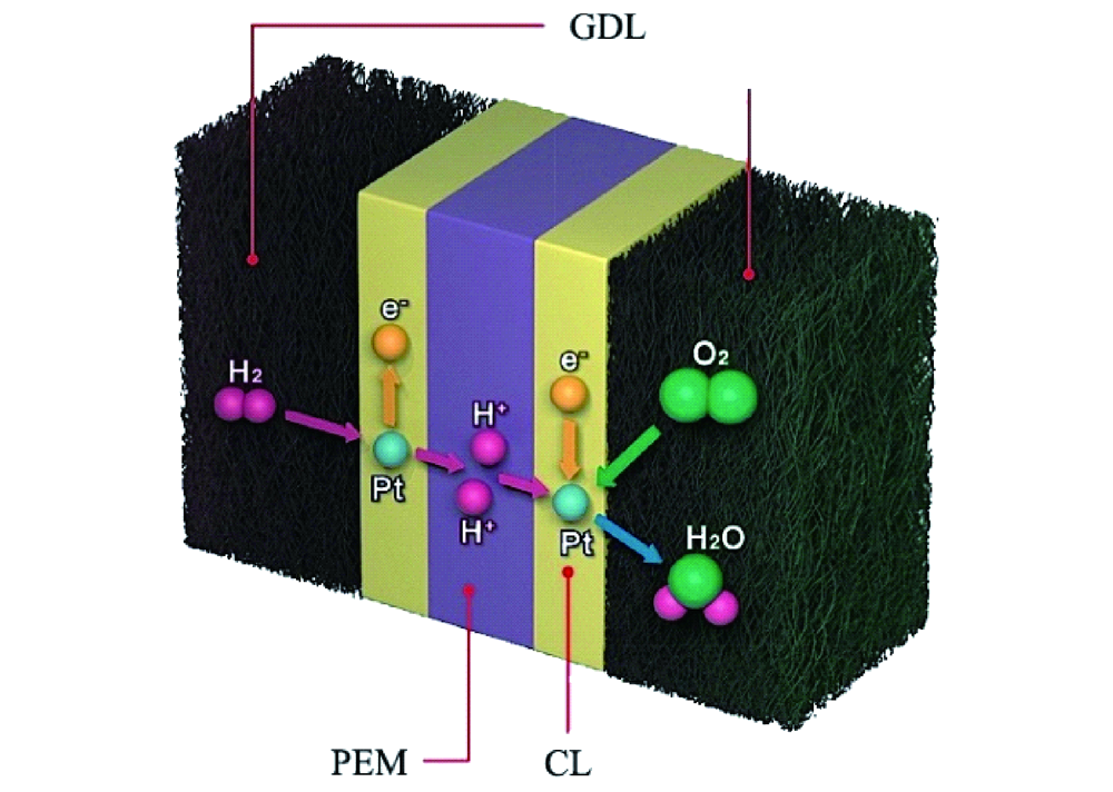
Hydrogen fuel cells are often regarded as a key element in the green energy transition. Their efficiency is double the thermochemical energy conversion of internal combustion engines. Hydrogen fuel cells convert the chemical energy of hydrogen and oxygen directly into electricity and water. Hence, water plays a central role in fuel cells. It supports ion transport and participates is product of the reaction itself. In an anion exchange membrane fuel cell (AEMFC), for the oxygen reduction reaction to take place, the water in the anode catalyst layer (ACL) must diffuse to the cathode catalyst layer (CCL). In summary, water management is required to remove water from the ACL for higher efficiency of hydrogen diffusion and to balance the water in the entire membrane electrode assembly (MEA).

Significant research efforts have been made to achieve conditions that is suitable for both the anode and cathode in AEMFC. Asymmetric humidification of reactant gases was proposed to be beneficial to achieve well equilibrated water balance between the two electrodes. At higher temperatures, excess anode water evaporates. It also causes deficiencies at the cathode which also requires water to function. To counteract this, a new system that controls the back pressure at the anode and cathode was introduced. However, external control mechanisms (active control) increase the complexity of the system control.

This is where a passive control system involving MEA modification comes into the picture. Moisture control in a fuel cells can be achieved by designing a suitable gas diffusion layer. Adopting different types of hydrophobic materials for the anode and hydrophilic for the cathode can improve overall fuel cell performance. Poly ethylene tetrafluoroethylene (PTFE) copolymer ion exchange membranes, such as Nafion™ have high water mobility. This property can help water back diffusion to avoid anode flooding while preventing dehydration of the cathode. Designing a gradient microstructure or ionomer content within the CCL could also be useful to improve cell performance and durability.

Recent research published in the journal Cell Reports Physical Science addresses these questions. The presented study was carried out to assess a multi-layer CCL design with the gradient capillary force which has a driving effect on water to solve the water balance problem of anodes in AEMFC. For the purpose of the study, platinum on carbon and platinum-ruthenium on carbon were selected as anode catalysts. Ruthenium increases the hydrogen oxidation reaction activity and possesses beneficial structural properties. Water management and performance of AEMFC would be influenced by the structure of the ACL.

Microstructure analysis of ACLs

ACLs composed of different layers of Pt/C and PtRu/C and a mixed version with a similar thickness of around 9-10 µm were analyzed with energy-dispersive X-ray spectroscopy (EDX).

Pt/C ACL had pores of less than 150 nm while PtRu/C catalysts pores ranged between 300-400 nm. The mixed ACL had a pore size <200 nm.

The researchers concluded that Pt/C and PtRu/C ACL had a stratified and gradient pore size distribution spanning across the anion exchange membrane and the gas diffusion layer. The mixed ACL, however, had a homogenous pore structure throughout the MEA.
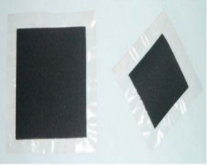
Membrane electrode assembly using a polymer electrolyte membrane

Moisture adsorption and desorption behavior of ACLs

To investigate moisture adsorption and desorption, the change of the fuel cell’s moisture content was checked with regards to different levels of relative humidity.

It was observed that the moisture content level increased by up to 50% mass weight along with an increase in relative humidity from 20% to 80%.

With an extended equilibrium time for a relative humidity of 80%, the moisture content of Pt/PtRu and PtRu/Pt ACL began to decrease. This was evidence for the self-adjusting water management behavior.

Desorption at a relative humidity of 60% was done. The water content in ACL showed rapid adsorption and slow-release properties at each relative humidity setting.

Physical adjustment of water behavior was observed in PtRu/Pt ACLs. This was attributed to gradient nano-pores and promoted water transport when water was generated within the ACLs during the electrochemical reactions. It would facilitate fuel cells operation at high current density.

Fuel cell performance of ACLs

To assess the structural effect on water management during operation, fuel cell performance was investigated at different relative humidity and temperature levels.

With increasing relative humidity from 40% to 80%, an increase of the maximum power density was observed as well while the temperature remained constant at 50°C. This was due to higher ionic conductivity at high membrane hydration.

At relative humidity of 100%, a maximum power density of the Pt/PtRu MEA and the mixed MEA decreased, however. The inverted MEA version using PtRu/Pt an increase to 243 mW/cm2 was observed. This suggested that the moisture desorption ability of PtRu/Pt MEA promoted mass transfer during fuel cell operation.

At a temperature of 60°C and 100% relative humidity, the maximum power density of PtRu/Pt reached 252 mW/cm2.

A durability test was conducted for PtRu/Pt MEA. It showed that after continuous operation for more than 16 hours at 100 mA/cm2 the voltage drop was <4%.

Conclusion

It became clear from the tests that the PtRu/Pt anode catalyst layer with its homogenous layer had a better self-adjustment capability for fuel cell water management. The gradient nanopore structure of the catalyst layer made it possible to transport water through the capillary effect. Excess water at the anode could either be transported towards the cathode where it would be used for reaction or towards the gas diffusion layer for its removal prevented flooding. Moreover, this catalyst layer made from PtRu/Pt showed better performance abilities too.

At Frontis Energy we think that this could resolve the issues faced with water management in the fuel cells. Since it is a passive control system that involves modifying the design of the fuel cells internally, intricate external systems could be replaced or complemented. The study certainly helps future fuel cell automation as an interesting new aspect of fuel cell design was discovered that could make them smarter.
Reference: Self-adjusting anode catalyst layer for smart water management in anion exchange membrane fuel cells, Cell Reports Physical Science, Volume 2, Issue 3, 24 March 2021, 100377

Posted on

Green alternative to fluorinated membranes in PEM fuel cells

Polymer electrolyte membrane (PEM) fuel cells have high power density, low operational temperatures. If PEM runs on green hydrogen, it doesn’t even emit carbon. But their fabrication requires perfluorinated sulfonic acid (PFSA) polymers as an electrolyte separator membrane and as an ionomer in the electrode, which is quite expensive. Nafion® is the leading commercial PFSA polymer in the market. However, its manufacturing is costly as well as environmentally hazardous. Therefore, low-cost, environmentally friendly PFSA polymer substitutes are the primary goals for the fuel cell scientific community worldwide.

Researchers of the Texas A&M University and Kraton Performance Polymers Inc. experimented using NEXAR ™ polymer membranes in hydrogen fuel cells, studying different ion exchange capacities. NEXAR ™ polymer membranes are commercially available sulfonated pentablock terpolymers. They published the results in the Journal of Membrane Science . Previous studies showed that changing the ion exchange capacity, that is, the degree of sulfonation of NEXAR ™ membranes can alter the nanoscale morphology and significantly affect mechanical properties. This may influence fuel cell performance. Hence, this polymer may be used as a membrane alternative to Nafion® in fuel cells.

Experimental procedure

  1. Materials under consideration: three different variants of the polymer were taken up each with different Ion Exchange Capacities (IECs: 2.0, 1.5, and 1.0 meq / g), which were named NEXAR ™ -2.0, NEXAR ™ -1.5, and NEXAR ™ – 1.0 respectively.
  2. NEXAR ™ membrane preparation: NEXAR ™ membranes were fabricated by casting the NEXAR ™ solutions onto a silicon-coated Mylar PET film using an automatic film applicator under ambient conditions. Two different sizes were manufactured for measuring mechanical properties and conductivity.
  3. NEXAR ™ membrane characterization: mechanical properties using the size 25 mm (L) x 0.5 mm (W) membrane as test pieces were determined and for proton conductivity test pieces of size 30 mm (L) x 10 mm (W) were tested upon.
  4. Nafion® electrode fabrication: conventional Nafion® electrodes were also fabricated as controls to conduct simultaneous tests.
  5. NEXAR ™ electrode fabrication: NEXAR ™ electrodes were prepared in 2 ways for the 2-part study, each with a different composition.
  6. Electrode characterization: electrode profiling was done using a scanning electron microscopy (SEM).
  7. Membrane electrode assembly (MEA) and fuel cell tests: MEAs were fabricated by placing the membrane in between two catalyst-coated gas diffusion layers (anode and cathode) and heat pressing. The entire fuel cell assembly consisted of an MEA, two gaskets, and two flow plates placed between copper current collectors followed by end plates all held together by bolts. Fuel cell performance tests were conducted under ambient pressure with saturated (100% RH) anode and cathode flow rates of 0.43 L / min hydrogen and 1.02 L / min oxygen respectively.
  8. Electrochemical impedance spectroscopy (EIS): electrochemical impedance spectroscopy was performed after the fuel cell tests and the results analyzed.

Results

NEXAR ™ -2.0 and NEXAR ™ -1.5 had a similar proton conductivity at all temperatures, suggesting that there is a maximum limit in proton conductivity. On the contrary, NEXAR ™ membranes, when compared to Nafion® NR-212 membranes , have sufficient proton conductivity to translate into high power density hydrogen fuel cell performance.

However, NEXAR ™ -2.0 and NEXAR ™ -1.5 membranes (with Nafion® as Ionomer) did not exhibit expected fuel cell performance at all fuel cell operating conditions (temperature, pressure, voltage and humidity). Surprisingly, the NEXAR ™ -1.0 membrane (with Nafion® as Ionomer) showed expected fuel cell performance across all fuel cell operating conditions and comparable power densities to Nafion® , suggesting that NEXAR ™ -1.0 may be a viable alternative to Nafion® in hydrogen fuel cells.

During fuel cell operation the NEXAR ™ -1.0 / NEXAR ™ -1.0 membrane-ionomer was thermally and mechanically stable. These results were supported by the power density results, where MEAs with NEXAR ™ -1.0 membrane-ionomers performed better than all the other MEAs.

From the above-mentioned results it became evident that the NEXAR ™ -1.0 variant was the optimal contender to substitute current state-of-the-art PFSA polymers.

Further, to understand the impact of the NEXAR ™ -1.0 ionomer on fuel cell performance, the composition of the ionomer and solvent mixture ratios in the catalyst ink solution were modified and investigated. Results suggested that NEXAR ™ -1.0 as an ionomer behaves similarly to Nafion® ionomers in fuel cell electrodes.

SEM analysis suggested that the amount of ionomer has a significant impact on the binding of ionomer to the catalyst particles, and consequently on the catalyst layer morphology. Therefore, there is an optimum catalyst / ionomer ratio of 2/1 for the Pt / C ionomer using NEXAR ™ -1.0 in fuel cell electrodes.

Conclusions

Ultimately, NEXAR ™ -1.0 is a potentially commercially viable greener substitute to Nafion® as a membrane and ionomer in PEM Fuel cell applications due to its high conductivity, however; alternative block compositions may improve the properties of the polymer to minimize resistances within the fuel cell to match the performance of Nafion® .

Overall Nafion® / Nafion® MEAs still showed the highest fuel cell performance when overall performance was taken into account but alternative hydrocarbon-based polymer compositions for the NEXAR ™ Polymer might provide a future non-fluorinated polymer as a  Nafion® substitute for PEM fuel cells .

Way forward

More analysis is required to perhaps get an accurate approximation of what variant of the NEXAR ™ polymer might cut the mark, future research may be focused upon exploring variants of Ion Exchange Capacities ranging from say 1 meq / g to 1.5 meq / g. But for now, it can be said that NEXAR ™ polymer shows promise as a viable replacement as a non-fluorinated membrane, and perhaps further research with more iterations of mechanical specs as well as chemical specs of the material we might witness a breakthrough.

Reference: https://doi.org/10.1016/j.memsci.2021.119330 : Sulfonated pentablock terpolymers as membranes and ionomers in hydrogen fuel cells , Journal of Membrane Science, 2021, 119330