Direct ethanol fuel cells (DEFCs) are fuel cells that run on ethanol to directly produce electrical power. Despite having much to offer they have not been forayed into. Ethanol can be made from biomass by yeasts and its oxidation products – CO2 and H2O – are hence environmentally friendly. The application of DEFCs could be a lucrative solution for vehicles due to the energy efficiency if mass-produced. Our current infrastructure for combustion fuels is ready for ethanol. DEFC usage would therefore be a sustainable and environment-friendly alternative to current internal combustion engines. Moreover, ethanol is liquid, which facilitates distribution, storage and use.
According to studies sponsored by International Energy Agency (IEA), DEFCs deliver high power densities, culminating between 50 to 185 mW / cm2. Currently, DEFCs face multiple challenges such as slow redox kinetics, limited performance, and the high cost of electrocatalysts needed for DEFCs.
In a DEFC, the two key reactions are:
Ethanol Oxidation Reaction (EOR)
Oxygen Reduction Reaction (ORR)
Their sluggish rates have prevented widespread adoption of this technology. State-of-the-art DEFCs require expensive platinum-based materials to catalyze these reactions. Yet, they do not completely oxidize ethanol to CO2 to complete the EOR reaction, limiting the energy efficiency. One way to fix this issue is to separate and re-inject the unreacted ethanol. Since this adds more engineering to the fuel cell, a better solution is to find more efficient catalysts. Hence, to realize the true potential of DEFCs, is to find cheaper and more active catalysts for the two reactions in DEFCs.
The researchers at the University of Central Florida and their colleagues experimented on Pd–N–C catalyst and attempted to improve catalyst performance by introducing fluorine atoms. The team used alkaline membranes and platinum-free catalysts. Not only were these more cost-effective but also produced a high power output.
Previous research on electrocatalytic systems revealed that the local coordination environment (LCE) of the electrode surface is pivotal in tuning the activity of electrocatalysts made of carbon-supported metal nanoparticles. The study showed that introducing fluorine atoms in Pd–N–C catalysts regulated the LCE around the Pd, improving both activity and durability for the two key reactions. This improved the catalytic performance, and ultimately the fuel cell’s performance.
The new study demonstrated that fluorine doping rearranged the electron structure of the fuel cell catalyst. This substantially improved power density and ultimately the performance of the DEFC when compared with present-day benchmark catalysts. The experimental results on long-term stability demonstrated promising advancements towards practical applications of such catalysts in DEFCs.
Results
Upon experimental analysis, it was found that the fluorine atoms in the catalyst weakened carbon-nitrogen bond and pushed the N atoms towards palladium. This electron translocation efficiently regulated the LCE of palladium by forming palladium-nitrogen active sites for catalytic reactions.
The N-rich palladium surface promoted carbon-carbon bond cleavage and enabled complete ethanol oxidation. During the ORR, the N-rich palladium surface surface not only weakened CO2 adsorption but also created more accessible catalytic sites for rapid O2 adsorption.
According to the authors, a commonly occurring problem in DEFCs – the inability to complete the two key reactions – has been resolved. Their catalyst enhanced the overall performance of the fuel cell. The addition of fluorine also enhanced the durability of the catalyst by reducing the corrosion of carbon materials as well as inhibiting palladium migration and aggregation.
When the novel catalyst was tested in a DEFC, an output maximum power density of 0.57 W/cm2 was obtained. The fuel cell was stable for more than 5,900 hours. The proposed strategy, when experimented with using other carbon-supported metal catalysts, also gave improved results in activity and stability.
Outlook
The main shortcoming of DEFCs running in the alkaline condition is their durability. Currently, it is not sufficient for practical applications. Moreover, the anion-exchange membranes in use have two issues:
Structural stability of membrane is insufficient for long-term use
Carbonation occurs in presence of CO2 due to its reaction with hydroxide ions, ultimately degrading the catalyst.
Albeit stable for remarkable 5,900 hours, the membrane was replaced after 1,200 hours in the presented study. Since replacing membranes require complete disassembly of the cell, this is not a long-term practical solution.
Hence, there must be further research on increasing ionic conductivity and stability of anionic membranes for practical use of DEFC in alkaline conditions. Ideally, the hydroxide solution used to increase ionic conductivity is avoided to preserve energy density and reduce the complexity of the device. Solid oxide fuel cells offer a solution for these problems since the fuel is oxidized in gaseous form but their ceramic membrane are too fragile for mobile applications.
The current experiment makes significant strides in improving power density in DEFCs much more than any state-of-the-art DEFCs. The way ahead is further research to overcome these smaller obstacles in the long-term use of anionic membranes.
Carbon black with abundant oxygen functional groups and melamine (C3H6N6) were mixed and ground, and finally pyrolyzed. After cooling to room temperature, N–C was obtained by washing with ethanol and water. The same method was used to synthesize P–C, S–C, B–C, and F–C from sodium hypophosphite anhydrous, sulfur powder, boric acid, and polyvinylidene difluoride.
Synthesis of hetero-atom fluorine-doped carbon catalysts
N–C and polyvinylidene difluoride were mixed and ground before adding them into a solution of acetone and water. After ultra sound treatment, the mixture was refluxed in an oil bath until fully dried. The mixture was then pyrolyzed and after cooling to room temperature, the samples were washed with ethanol and ultrapure water, followed by a vacuum to obtain the fluorinated catalyst support. The same method was used for the other precursors.
A microwave reduction method was used to synthesize palladium catalyst on the catalyst support. The content of palladium in all samples was kept at 1.0%, which was determined and double-confirmed by X-ray spectroscopy and inductively coupled plasma.
Electrochemical characterizations
For the electrical measurements, either a glassy carbon ring-disc electrode or rotating ring-disc electrode were used. The Fumasep membrane was used as an anion-exchange membrane, modified to change it to a hydroxide environment.
Reference
Chang et al., 2021, Improving Pd–N–C fuel cell electrocatalysts through fluorination-driven rearrangements of local coordination environment. Nature Energy 6, 1144–1153 https://doi.org/10.1038/s41560-021-00940-4
Hydrogen fuel cells are often regarded as a key element in the green energy transition. Their efficiency is double the thermochemical energy conversion of internal combustion engines. Hydrogen fuel cells convert the chemical energy of hydrogen and oxygen directly into electricity and water. Hence, water plays a central role in fuel cells. It supports ion transport and participates is product of the reaction itself. In an anion exchange membrane fuel cell (AEMFC), for the oxygen reduction reaction to take place, the water in the anode catalyst layer (ACL) must diffuse to the cathode catalyst layer (CCL). In summary, water management is required to remove water from the ACL for higher efficiency of hydrogen diffusion and to balance the water in the entire membrane electrode assembly (MEA).
Significant research efforts have been made to achieve conditions that is suitable for both the anode and cathode in AEMFC. Asymmetric humidification of reactant gases was proposed to be beneficial to achieve well equilibrated water balance between the two electrodes. At higher temperatures, excess anode water evaporates. It also causes deficiencies at the cathode which also requires water to function. To counteract this, a new system that controls the back pressure at the anode and cathode was introduced. However, external control mechanisms (active control) increase the complexity of the system control.
This is where a passive control system involving MEA modification comes into the picture. Moisture control in a fuel cells can be achieved by designing a suitable gas diffusion layer. Adopting different types of hydrophobic materials for the anode and hydrophilic for the cathode can improve overall fuel cell performance. Poly ethylene tetrafluoroethylene (PTFE) copolymer ion exchange membranes, such as Nafion™ have high water mobility. This property can help water back diffusion to avoid anode flooding while preventing dehydration of the cathode. Designing a gradient microstructure or ionomer content within the CCL could also be useful to improve cell performance and durability.
Recent research published in the journal Cell Reports Physical Science addresses these questions. The presented study was carried out to assess a multi-layer CCL design with the gradient capillary force which has a driving effect on water to solve the water balance problem of anodes in AEMFC. For the purpose of the study, platinum on carbon and platinum-ruthenium on carbon were selected as anode catalysts. Ruthenium increases the hydrogen oxidation reaction activity and possesses beneficial structural properties. Water management and performance of AEMFC would be influenced by the structure of the ACL.
Microstructure analysis of ACLs
ACLs composed of different layers of Pt/C and PtRu/C and a mixed version with a similar thickness of around 9-10 µm were analyzed with energy-dispersive X-ray spectroscopy (EDX).
Pt/C ACL had pores of less than 150 nm while PtRu/C catalysts pores ranged between 300-400 nm. The mixed ACL had a pore size <200 nm.
The researchers concluded that Pt/C and PtRu/C ACL had a stratified and gradient pore size distribution spanning across the anion exchange membrane and the gas diffusion layer. The mixed ACL, however, had a homogenous pore structure throughout the MEA.
Membrane electrode assembly using a polymer electrolyte membrane
Moisture adsorption and desorption behavior of ACLs
To investigate moisture adsorption and desorption, the change of the fuel cell’s moisture content was checked with regards to different levels of relative humidity.
It was observed that the moisture content level increased by up to 50% mass weight along with an increase in relative humidity from 20% to 80%.
With an extended equilibrium time for a relative humidity of 80%, the moisture content of Pt/PtRu and PtRu/Pt ACL began to decrease. This was evidence for the self-adjusting water management behavior.
Desorption at a relative humidity of 60% was done. The water content in ACL showed rapid adsorption and slow-release properties at each relative humidity setting.
Physical adjustment of water behavior was observed in PtRu/Pt ACLs. This was attributed to gradient nano-pores and promoted water transport when water was generated within the ACLs during the electrochemical reactions. It would facilitate fuel cells operation at high current density.
Fuel cell performance of ACLs
To assess the structural effect on water management during operation, fuel cell performance was investigated at different relative humidity and temperature levels.
With increasing relative humidity from 40% to 80%, an increase of the maximum power density was observed as well while the temperature remained constant at 50°C. This was due to higher ionic conductivity at high membrane hydration.
At relative humidity of 100%, a maximum power density of the Pt/PtRu MEA and the mixed MEA decreased, however. The inverted MEA version using PtRu/Pt an increase to 243 mW/cm2 was observed. This suggested that the moisture desorption ability of PtRu/Pt MEA promoted mass transfer during fuel cell operation.
At a temperature of 60°C and 100% relative humidity, the maximum power density of PtRu/Pt reached 252 mW/cm2.
A durability test was conducted for PtRu/Pt MEA. It showed that after continuous operation for more than 16 hours at 100 mA/cm2 the voltage drop was <4%.
Conclusion
It became clear from the tests that the PtRu/Pt anode catalyst layer with its homogenous layer had a better self-adjustment capability for fuel cell water management. The gradient nanopore structure of the catalyst layer made it possible to transport water through the capillary effect. Excess water at the anode could either be transported towards the cathode where it would be used for reaction or towards the gas diffusion layer for its removal prevented flooding. Moreover, this catalyst layer made from PtRu/Pt showed better performance abilities too.
At Frontis Energy we think that this could resolve the issues faced with water management in the fuel cells. Since it is a passive control system that involves modifying the design of the fuel cells internally, intricate external systems could be replaced or complemented. The study certainly helps future fuel cell automation as an interesting new aspect of fuel cell design was discovered that could make them smarter.
Despite a common belief, very little is known about the structure of water and interfacial interactions. Interfacial water that is adsorbed on the surface of the hydrophilic materials is formed by both water-surface and water-water interactions. It has been discovered that the interfacial water differs from the water in bulk and can exclude solutes and microspheres, and hence it is termed an exclusion zone (EZ). EZ water is known to have a higher refractive index, viscosity, and light adsorption at 270 nm. Charge separation is also caused by water-surface interactions. For example, the water EZ near Nafion™ membranes has an electrical potential of −200 mV.
Studies showed that electromagnetic energy can affect interfacial water. Infrared (IR) energy can cause expansion of the size of the EZ leading to charge separation. This study was conducted by researchers of the University of Washington with IR light of varying intensities and wavelengths to see if they can accelerate the process and bring protons into bulk water. The scientists attempted to shed light on the complex nature of aqueous interfaces.
Experimental analysis
Materials used:
Deionized (DI) water with the resistivity of 18.2 MΩ × cm was purified with a Barnstead D3750 Nanopure Diamond water system. Other materials were a Nafion™ N117 membrane, a potassium phosphate buffer, a pH dye and carboxylate microspheres (1 µm diameter in a 2.5% suspension)
Sample preparation:
Carboxylate microsphere suspensions with a microsphere-to-water volume ratio of 1:300 and pH-sensitive dye with the dye-to-water volume ratio of 1:20 for better visualization were added.
Due to carbon dioxide absorption the water had a slightly acidic pH of 6.35 and was neutralized. To stabilize the pH, a 1 molar potassium phosphate buffer of pH 7.0 made from equal volumes of 1 molar K2HPO4 and KH2PO4 solutions and added at a final concentration of 1 mM.
A Nafion™ membrane of 3 × 20 mm size was pre-soaked in 1 liter of DI water for 24 hours before use.
Control and irradiation experiments:
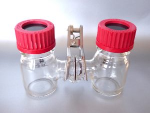
A thick plastic block chamber was injected with the 1 mL water the containing buffer solution, pH dye, and microspheres. The chamber consisted of a glass slide and a groove in the central vertical plane of the chamber was used to hold the Nafion™ membrane. This setup was placed on the stage of an inverted microscope for observation over 10 min.
For irradiation experiments, mid-infrared (MIR) LED wavelengths at 3.0 μm, and three near-infrared (NIR) LEDs of different wavelengths were used. It was placed 2 mm above the water level in the chamber. The light was kept as continuous as possible with constant emission power. It shone for 5 mins onto the water surface. The temperature of the water samples was obtained using infrared cameras.
Results
Water zones differ from bulk water
Interfacial water excluded dye and microspheres by forming EZ water next to Nafion™. A red zone with of pH 4 was formed beyond the EZ water called proton zone (PZ). The researchers concluded that the protons accumulated there due to growing interfacial water. With the time of contact between Nafion™ and water progressing, the EZ size was doubled as did the PZ. The microspheres drifted away from Nafion™ with time.
Stability of EZ size and PZ size
It was evident from the observation that EZ water was not caused by the substance flowing out of Nafion™. It is believed that the ice-like structure of interfacial water cause EZ and PZ water. This network of hexagonal structure, several hundred microns. Electrostatic attractions exist between the EZ water layers.
Effect of IR radiation on EZ water and PZ water
The proton concentration in PZ water increased with IR intensity along with the size of EZ and PZ. Higher IR intensities weaken the OH bonds aiding those molecules to participate in EZ expansion. IR radiation also caused thermodiffusion with carboxylate microspheres moving away from the IR light spot with increasing intensity.
Effect of NIR on EZ and PZ waters
The study of the effect of NIR on interfacial water can help to better understand light therapy. Red wavelengths and NIR wavelengths are considered suitable due to their ability to deeply penetrate tissue. Light therapy aids in the synthesis of adenosine tri-phosphate (ATP), the universal biological energy currency. This could have medical benefits. Interfacial water could act as a photoreceptor in light therapy, as cells contain macromolecules and organelles. The use of NIR to establish a proton gradient requires further investigation.
Conclusions
The research showed that the EZ and PZ zones in interfacial water stabilize after five minutes and that infrared radiation can considerably increase the size of these zones with intensity. This is possibly due to the special nature of water present on hydrophilic material surfaces.
It is also evident that IR radiation can help in building up microsphere-free zones − a phenomenon that in turn creates proton-rich zones. This is also responsible for charge separation in interfacial water. In summary, some of the mysteries regarding the complexity of interfacial water, EZ, and PZ water zones have been clarified but much remains to be studied.
Outlook
As always, further research to understand the nature of EZ and PZ of water is required. For example the viability and the possibility of the use of NIR for light therapy using interfacial water as a photoreceptor should to be studied. This applications has the potential to make a positive impact on medical applications.
References: https://doi.org/10.1016/j.colcom.2021.100397 : Effect of infrared radiation on interfacial water at hydrophilic surfaces, Colloid and Interface Science Communications, Volume 42 , May 2021, 100397
Polymer electrolyte membrane (PEM) fuel cells have high power density, low operational temperatures. If PEM runs on green hydrogen, it doesn’t even emit carbon. But their fabrication requires perfluorinated sulfonic acid (PFSA) polymers as an electrolyte separator membrane and as an ionomer in the electrode, which is quite expensive. Nafion® is the leading commercial PFSA polymer in the market. However, its manufacturing is costly as well as environmentally hazardous. Therefore, low-cost, environmentally friendly PFSA polymer substitutes are the primary goals for the fuel cell scientific community worldwide.
Researchers of the Texas A&M University and Kraton Performance Polymers Inc. experimented using NEXAR ™ polymer membranes in hydrogen fuel cells, studying different ion exchange capacities. NEXAR ™ polymer membranes are commercially available sulfonated pentablock terpolymers. They published the results in the Journal of Membrane Science . Previous studies showed that changing the ion exchange capacity, that is, the degree of sulfonation of NEXAR ™ membranes can alter the nanoscale morphology and significantly affect mechanical properties. This may influence fuel cell performance. Hence, this polymer may be used as a membrane alternative to Nafion® in fuel cells.
Experimental procedure
Materials under consideration: three different variants of the polymer were taken up each with different Ion Exchange Capacities (IECs: 2.0, 1.5, and 1.0 meq / g), which were named NEXAR ™ -2.0, NEXAR ™ -1.5, and NEXAR ™ – 1.0 respectively.
NEXAR ™ membrane preparation: NEXAR ™ membranes were fabricated by casting the NEXAR ™ solutions onto a silicon-coated Mylar PET film using an automatic film applicator under ambient conditions. Two different sizes were manufactured for measuring mechanical properties and conductivity.
NEXAR ™ membrane characterization: mechanical properties using the size 25 mm (L) x 0.5 mm (W) membrane as test pieces were determined and for proton conductivity test pieces of size 30 mm (L) x 10 mm (W) were tested upon.
Nafion® electrode fabrication: conventional Nafion® electrodes were also fabricated as controls to conduct simultaneous tests.
NEXAR ™ electrode fabrication: NEXAR ™ electrodes were prepared in 2 ways for the 2-part study, each with a different composition.
Electrode characterization: electrode profiling was done using a scanning electron microscopy (SEM).
Membrane electrode assembly (MEA) and fuel cell tests: MEAs were fabricated by placing the membrane in between two catalyst-coated gas diffusion layers (anode and cathode) and heat pressing. The entire fuel cell assembly consisted of an MEA, two gaskets, and two flow plates placed between copper current collectors followed by end plates all held together by bolts. Fuel cell performance tests were conducted under ambient pressure with saturated (100% RH) anode and cathode flow rates of 0.43 L / min hydrogen and 1.02 L / min oxygen respectively.
Electrochemical impedance spectroscopy (EIS): electrochemical impedance spectroscopy was performed after the fuel cell tests and the results analyzed.
Results
NEXAR ™ -2.0 and NEXAR ™ -1.5 had a similar proton conductivity at all temperatures, suggesting that there is a maximum limit in proton conductivity. On the contrary, NEXAR ™ membranes, when compared to Nafion® NR-212 membranes , have sufficient proton conductivity to translate into high power density hydrogen fuel cell performance.
However, NEXAR ™ -2.0 and NEXAR ™ -1.5 membranes (with Nafion® as Ionomer) did not exhibit expected fuel cell performance at all fuel cell operating conditions (temperature, pressure, voltage and humidity). Surprisingly, the NEXAR ™ -1.0 membrane (with Nafion® as Ionomer) showed expected fuel cell performance across all fuel cell operating conditions and comparable power densities to Nafion® , suggesting that NEXAR ™ -1.0 may be a viable alternative to Nafion® in hydrogen fuel cells.
During fuel cell operation the NEXAR ™ -1.0 / NEXAR ™ -1.0 membrane-ionomer was thermally and mechanically stable. These results were supported by the power density results, where MEAs with NEXAR ™ -1.0 membrane-ionomers performed better than all the other MEAs.
From the above-mentioned results it became evident that the NEXAR ™ -1.0 variant was the optimal contender to substitute current state-of-the-art PFSA polymers.
Further, to understand the impact of the NEXAR ™ -1.0 ionomer on fuel cell performance, the composition of the ionomer and solvent mixture ratios in the catalyst ink solution were modified and investigated. Results suggested that NEXAR ™ -1.0 as an ionomer behaves similarly to Nafion® ionomers in fuel cell electrodes.
SEM analysis suggested that the amount of ionomer has a significant impact on the binding of ionomer to the catalyst particles, and consequently on the catalyst layer morphology. Therefore, there is an optimum catalyst / ionomer ratio of 2/1 for the Pt / C ionomer using NEXAR ™ -1.0 in fuel cell electrodes.
Conclusions
Ultimately, NEXAR ™ -1.0 is a potentially commercially viable greener substitute to Nafion® as a membrane and ionomer in PEM Fuel cell applications due to its high conductivity, however; alternative block compositions may improve the properties of the polymer to minimize resistances within the fuel cell to match the performance of Nafion® .
Overall Nafion® / Nafion® MEAs still showed the highest fuel cell performance when overall performance was taken into account but alternative hydrocarbon-based polymer compositions for the NEXAR ™ Polymer might provide a future non-fluorinated polymer as a Nafion® substitute for PEM fuel cells .
Way forward
More analysis is required to perhaps get an accurate approximation of what variant of the NEXAR ™ polymer might cut the mark, future research may be focused upon exploring variants of Ion Exchange Capacities ranging from say 1 meq / g to 1.5 meq / g. But for now, it can be said that NEXAR ™ polymer shows promise as a viable replacement as a non-fluorinated membrane, and perhaps further research with more iterations of mechanical specs as well as chemical specs of the material we might witness a breakthrough.
Reference: https://doi.org/10.1016/j.memsci.2021.119330 : Sulfonated pentablock terpolymers as membranes and ionomers in hydrogen fuel cells , Journal of Membrane Science, 2021, 119330
In the order to address the global need for renewable and clean energy sources, salinity-gradient energy harvested by reverse electrodialysis (RED) is attracting significant interest in recent years. In addition, brine solution coming from seawater desalination is currently considered as a waste; however thanks to its high salinity it can be exploited as a valuable resource to feed RED. RED is an engineered adaptation of nature’s osmotic energy production where ions flow pass the cell membrane in order to produce the universal biological currency ATP. This energy is also harvested by the RED technology.
Now, more than ever there is need for sustainable and environmentally friendly technological solutions in order to keep up with ever growing demand for clean water and energy. The traditional linear way “produce and throw away” does no longer serve the society anymore and the new approach of circular economy has take a place, where any waste can be considered as a valuable resource for another process. In this respect, reverse electrodialysis is a promising electromembrane-based technology to generate power from concentrated solutions by harvesting the Gibbs free energy of mixing the solutions with different salinity. In particular, brine solutions produced in desalination plants, which is currently considered as a waste, can be used as concentrated streams in RED stack.
Avci et al. of the University of Calabria, Italy, have recently published their solution for brine disposal using RED-stack. They have realized that in order to maximize generated power, the high permselectivity and ion conductivity of membrane components in RED are essential. Although Nafion™ membranes are among the most prominent commercial cation exchange membrane solutions for electrochemical applications, no study has been done in its utilization toward RED processes. This was the first reported RED stack using Nafion™ membranes.
A typical RED unit is similar to an electrodialysis (ED) unit, which is a commercialized technology. ED uses a feed solution and the electrical energy, while producing concentrate and dilute, separately. On the other side, RED uses concentrated and dilute solutions that are mixed together in a controlled manner in order to produce spontaneously electrical energy. In a RED stack, repeating cells comprised of alternating cation and anion exchange membranes that are selective for anions and cations. The salinity gradient over each ion exchange membrane creates a voltage difference which is the driving force for the process. The ion exchange membranes are one of the most important components of a RED stack.
The performance of Nafion™ membranes (Nafion™ 117 and Nafion™ 115) have been evaluated under a high salinity gradient conditions for the possible application in RED. In order to simulate the natural environments of RED operation, NaCl solution as well as multicomponent NaCl + MgCl2 have been tested.
Gross power density under high salinity gradient and the effect of Mg2+ on the efficiency in energy conversion have been evaluated in single cell RED using Nafion™ 117, Nafion™ 115, CMX and Fuji-CEM-80050 as cation exchange membranes. Two commercial cation exchange membranes – CMX and Fuji-CEM 80050, frequently used for RED applications, have served as benchmark.
The results show that under the condition of 0.5 M / 4.0 M NaCl solutions, the highest Pd,max was achieved using Nafion™ membrane. This result is attributed to their outstanding permselectivity compared to other CEMs. In the presence of Mg2+ ions, Pd,max reduction of 17 and 20% for Nafion™ 115 and Nafion™ 117 were recorded, respectively. Both membranes maintained their low resistance; however a loss in permselectivity was measured under this condition. Even though, it was reported that Nafion™ membranes outperformed other commercial membranes such as CMX and Fuji-CEM-80050 for RED application.
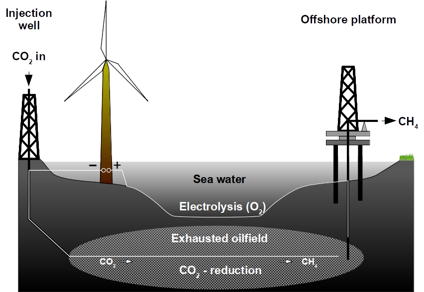
An abandoned or unproductive oilfield can be reused for methane production from CO2 using renewable electrical power. Exhausted oilfields can be reactors for the conversion of renewable energy to natural gas using microbes. To achieve this, an oilfield can be made electrically conductive and catalytically active to produce natural gas from renewable power sources. The use of natural gas is superior to any battery because of the existing infrastructure, the use in combustion engines, the high energy density and because it can be recycled from CO2. Oilfields are superior to any on-ground production because of the enormous storage capacities. They are already well explored and these geological formations underwent environmental risk assessments. Lastly, the microbial power-to-gas technology is already available.
Process summary
Whole process (end-to-end via methane)
50% electrical efficiency
Energy density of methane
180 kWh kg−1
Storage capacity per oilfield
3 GWh day−1
Charge/Discharge cycles
Unlimited
Investment (electrodes, for high densities)
$51,000 MW−1
Cost per kWh (>5,000 hours anode lifetime)
<$0.01 kWh−1
Electrolyte
Seawater
The Problem
To address the problem of storing renewable energy, batteries have been proposed as a possible solution. Lithium ion batteries have a maximum energy storage capacity of 0.3 kWh kg−1. To date, this is considered the best trade-off between cost and efficiency but these batteries are still too inefficient to replace gasoline, which has a capacity of about 13 kWh kg−1. This makes battery driven cars heavier than conventional cars. Lithium air batteries are considered a possible alternative because they can reach theoretical capacities of 12 kWh kg−1 but technical difficulties have prevented them from being used for transportation.
In contrast, methane has an energy density of 52 MJ kg−1 corresponding to 180 kWh kg−1 which is second only to hydrogen with 500 kWh kg−1, not counting in nuclear energy. This high energy density of methane and other hydrocarbons along with their facile usage, is the reason why they are used in combustion and jet engines that drive nearly all transportation to date. While electrical cars seem to be a tempting green alternative, the fact that combustion engines and the fueling infrastructure are so wide-spread makes it difficult to switch.
In addition to the difficulty of changing habits, battery-driven electrical cars need other limited natural resources such as lithium. To equip all 94 million automobiles produced worldwide in 2017, 3 mega tons lithium carbonate would need to be mined annually. This is nearly 10% of the entire recoverable lithium resources of 35 mega tons worldwide. Although lithium and other metals can be recycled, it is clear that metal based batteries alone will not build the bridge between green energy and traditional ways of transportation due to the low energy densities of metals. And this does not even take into account other energy demands such as industrial nitrogen fixation, aviation or heating.
For Germany, with its high proportion of renewable energy, fuel for cars is not the only problem. As renewable energy is generated in the north, but many energy consumers are in the south, the grid capacity is frequently reached during peak production hours. A steadier energy output can only be accomplished by decentralizing the production or by energy storage. To decentralize production, homeowners were encouraged to equip their property with solar panels or windmills. As tax incentives phase out, homeowners face the problem of energy storage. The best product for this group of customers so far are again lithium ion batteries but investment costs of $0.10 kWh−1 are still unattractive especially because these products store the energy as electricity which can only be used for a short time and is less efficient than natural gas when used for heating.
Natural gas is widely used as energy source today and the global energy infrastructure is designed for natural gas and other fossil fuels. Increasing demand and limited resources for these fossil fuels were the main drivers of oil and gas prices during the last years, slowed by the recent economic crises and hydraulic fracturing (fracking). The high oil price attracted investors to recover oil using techniques that become increasingly expensive and are environmental risks such as deep-sea drilling or tar sand extraction. Ironically, the high oil price made costly renewable energies an economically feasible alternative and helped driving down their cost. Since habits are difficult to change and building an entirely new infrastructure only for renewable energies does not seem economically feasible today while CO2 drives global warming, a more realistic solution needs to be found.
Microbial Power-to-Gas could be a bridging technology that integrates renewable energy into the existing fossil fuel infrastructure. It reaches break even in less than 2 years if certain preconditions are met. This is accomplished by integrating methane produced from renewable energy into the current oil and gas producing infrastructure. The principal idea is to use carbon instead of metals as energy carrier because of its high energy density when bound to hydrogen. The benefits are:
High energy density of 180 kWh kg−1 methane
Low investments due to existing infrastructure (natural gas, oilfield equipment)
Carbon is not a limited resource
Low CO2 footprint due to CO2 recycling
Methane is a transportation fuel
Methane is the energy carrier for the Haber-Bosch process
Inexpensive catalysts further reduce initial investments
Low temperatures due to bio-catalysis
No toxic compounds used
No additional environmental burden because existing oilfields are reused
The solution
Methane can be synthesized by microbes or chemically. Naturally, methane is produced by anaerobic (oxygen-free) microbial biomass decomposition. The energy for biomass synthesis is provided by sunlight or chemical energy like hydrogen. In the case of methanogens (methane producing microbes), energy is harvested after CO2 and hydrogen were released from biomass decomposition following a 1-to-4 stoichiometry:
CO2 + 4 H2 → CH4 + 2 H2O
Without microbes, methane is produced by the Nobel-prize winning Sabatier reaction and several attempts are currently underway to use it on industrial scale. It is necessary to split water into hydrogen and use this to reduce CO2 in the gas phase. A major drawback of the Sabatier reaction is the need for high temperatures around 385ºC, and a nickel catalyst that becomes quickly spent. Methanogens use iron-nickel enzymes called hydrogenases to harvest energy from hydrogen, but do so at ambient temperatures.
Power-to-Gas concept for exhausted oilfields. Electrolysis catalyzes water splitting inside the oilfield producing methane gas and O2.
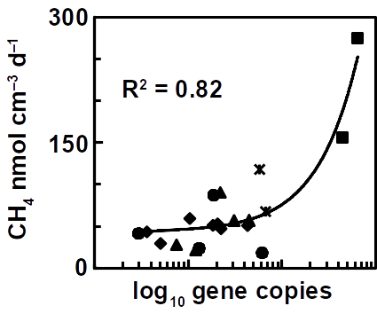
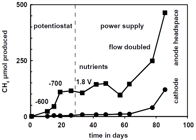
The future challenge will be to accelerate methane production rates as has been reported for a high temperature oilfield cultures. Besides increasing the temperature, the most obvious solution is to use a higher reactive surface and bringing both electrodes closer together. Using carbon brushes that are poor hydrogen catalysts but provide a higher surface for microbial attachment is one possibility. Methane production correlates with microbial cell numbers in the reactors.
The number of methanogens in microbial electrolysis reactors correlates with the electrode surface.
To overcome the problem of expensive carbon (and also steel) brushes for large scale applications,exhausted gas and oilfields could be used. They provide a high surface area and are usually economic liabilities and not assets. Methanogens inhabit oilfields where they carry out the final step in anaerobic petroleum degradation. Hence, oilfields can be seen as bioreactors at geological scale. Geological formations provide ideal conditions for producing, storing and extracting methane.
Open questions and potential solutions
Oilfield porespace volume
The Californian Summerland oilfield, for instance, has been abandoned and extensively studied in the past. It produced 27 billion barrels of oil and 2.8 billion m3 methane during its lifetime of 90 years. This maximum load of 3.5 billion m3 left the same volume of porespace filled with seawater behind. Only 2% of these pores are larger than 50 µm, which is necessary for microbial growth assuming dimensions of 1 x 2 µm of a methanogen cell. Experiments showed that the resulting 70 million m3 accessible porespace have a storage capacity of 35,000 TW. That is a lot of methane assuming a solubility of 0.74 kg methane m−3 seawater at 500 m water depth. All German off-shore windfarms together have a capacity of 7,000 MW. Obviously, the limiting factor is not the volumetric storage capacity of an oilfield.
Microbial methane production rates
But how fast can microbes produce methane in an hypothetical oilfield? Under optimal conditions, methanogens that grow on electrodes (typically the genus Methanobacterium or Methanobrevibacter) can produce methane at a rate of 100-200 nmol ml−1 day−1 (equals 2.24-4.48 ml l−1 day−1) depending on catalyst and potential. Using a production rate of 15 J ml−1 day−1 of methane (190 nmol ml−1 day−1), the entire microbially accessible oilfield (2%) has a capacity of 3.6 million MBtu per year. Microbes would theoretically consume 1 TWh per year for 3.6 million MBtu methane production if there were no losses and electrical power is translated into methane 1-to-1. A power generator of 121 MW would be sufficient to supply the entire oilfield at these rates. However, all German off-shore windfarms produce 7,000 MW meaning that only 3% off-peak power can be captured by our example oilfield. Therefore, the catalytic surface and activity must be increased to accelerate methane conversion rates.
Since methanogens produce methane from hydrogen, not only the 2% porespace big enough for cells can be used resulting in an increased catalytic surface to nearly 60%. A hydrogen catalyst needs to be found that does not out-pace methanogen growth to keep the reservoir pH within the limits of 6-8 required for methanogen growth. This hydrogen catalyst must be cheap and render an oilfield electrically conductive. A chemical formulation that mimics microbial hydrogen catalysis could be used. It has the potential to turn a non-conductive and non-catalytic oilfield into a conductive hydrogen catalyst sufficient to sustain methane production needed to store all of Germany’s electricity produced by off-shore windfarms. This catalyst is soluble in water when inactive. To become active, it coats mineral surfaces by precipitation that can be triggered by indigenous microbes or by electrical polarization. The investment would be $2.3 million per MW storage capacity ($16 billion for the entire 7,000 MW). Due to microbial growth, the catalytic activity of the system improves during operation and there is no need for the second component if an immediate production is not crucial. The investments made on the cathode side would then be as low as $600 per MW ($4.2 million for 7,000 MW).
Anodes
As the cathodic side of the reaction can be excluded as limiting factor, the anode needs to be designed. Several commercially available anodes such as mixed metal oxides (up to 750 A m−2) with platinum on carbon black or niobium anodes (Pt/C, 5-10 kA m−2) could be used. Anodes based on platinum are the most cost-efficient material available on the market. Investments made for Pt/C (10%, 6 mg cm−2) anodes will amount to $50,000 per MW ($350 million for 7,000 MW). However, the exact amount of Pt needed for the reaction still needs to be evaluated in an experiment because the corrosion rate at 2 V cell voltage is unknown. An often cited value for the lifetime of fuel cells is 5,000 hours and is used here to determine the costs per kWh. For 5,000 hours lifetime, the costs per kWh will be at the targeted limit of $0.01 but may be well below that because Pt/C anodes can be recycled and the Pt load may be reduced to 3 mg cm−2 (5%). Alternatively, steel anodes (SS316, 2.5 kA m−2, $54,000 per MW) can be used but it is unclear when steel anodes fail to electrolyze. In conclusion, the anodic side is the cost-driving factor. Hopefully, better water splitting anodes will lower these costs in future.
Cost estimation summary
Windfarms
Already in place
CO2 injection
Already occurred
Natural gas capturing equipment
Already in place
Microbial seed
Wastewater from oil rig
Cathode costs
$600 MW−1
Anode costs
$50,000 MW−1
Electrolyte (seawater)
Free
Total (>5,000 hours anode lifespan)
<$0.01 kWh−1
Energy and conversion efficiencies
The whole cell voltage for microbial power-to-gas reactions varies from 0.6 to 2.0 V, depending on cathodic rates, anodic corrosion and the presence of a membrane. Higher voltages will accelerate anode corrosion, again, making anodes the limiting factor. As the voltage decreases, methane production rates become slower but also more efficient. The voltage also depends on the pH of the oilfield. An oilfield that underwent CO2 injection as enhanced recovery method will have a low pH, providing better conditions for hydrogen production but not for microbial growth and must be neutralized using seawater. As stated above, the oilfield, being the cathode, is not limiting the the system. The use of Pt/C anodes eliminates the overpotential problem on the anode side. Hence, we can assume an ideal system that splits water at 1.23 V. However, the voltage is often 2 V due to anode and cathode overpotentials. Optimized cultures and cathodes produce about 190 nmol ml−1 day−1 methane which equals 0.15 J ml−1 day−1 using the energy of combustion of 0.8 MJ mol−1. The same electrolysis cell consumes 0.2 mW at a cell voltage of 2 V which equals 0.17 J ml−1 day−1 and the resulting energy efficiency is 91%. The anodes can be simple carbon brushes and the two chambers of the cell are separated by a Nafion™ membrane. The system can still be optimized by using Pt/C anodes and by avoiding membranes.
The overall electricity-methane-electricity efficiency also depends on the consumption side efficiency where methane is used in combustion engines and gas fired power plants. Such power plants frequently operate at efficiencies of 40- 60%. Assuming a reasonable power efficiency of 80% (see above), the overall electrical power recovery using gas fired power plants will be up to 50%. Besides the high efficiency of gas fired power plants, they are also easy to build and therefore contribute the a better power grid efficiency. Coal fired power plants can be upgraded to gas fired power plants.
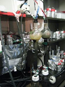
Experimental approach
The conversion efficiencies of charge (Coulombs) transported across the circuit are usually between 70-100% in these systems depending on the electrode material. Another efficiency limitation could arise from mass transport inhibition. Mass transport can be improved by pumping electrolyte adding more costs for pumping which still have to be determined. However, since most oilfields undergo seawater injection for enhanced oil recovery the additional cost may be negligible. The total efficiency has yet to be determined in scale-up experiments and will depend on the factors mentioned above.
The reactor simulates oilfield conditions using sand as filling material under continuous flow of electrolyte.
Controlling the pH is crucial. Alkaline pHs significantly impede hydrogen production and therefore methanogenesis. This can be addressed by a software that monitors the pH and adjusts the potential accordingly. Addition of acids is not desired as this drives the costs. The software can also act as potentiostat that then fully controls the methane production process. To test the process under more realistic conditions, a drill core from an oilfield must be obtained.
Results show methane production in the simulation reactor. The appearance of methane in the anode compartment was a result of flow from the cathode to the anode, carrying produced methane with it.
Return of investment of the microbial power-to-gas process
The the microbial power-to-gas process in unproductive oilfields is economically superior to all other storage strategies because of the low start-up and operating costs. This is achieved because the major investments are the installation of oil- and gas production equipment and renewable power plants which are already in place as a precondition. These investments break even in a short amount of time.
But how can the microbial Power-to-Gas process accelerate the return of investment in renewable energy? Only 8 out of 28 active off-shore windfarms reported their investment costs. These 8 produce roughly half the overall power of 1,600 MW corresponding to $7 billion. While the maximum production of an oilfield with unlimited supply of electricity would yield hypothetical 3.6 million MBtu natural gas per year resulting a return of $13 million per year the real production is limited by off-peak power generated by renewable energy production. Assuming that the maximum annual methane production corresponds to 10% excess electrical power, $15 million per year can by generated by selling 4.3 million MBtu methane per year on the market. These are $15 million that are not lost during off-peak shutdowns. Clearly, this conservative estimate can help to compensate the investment in renewable energy earlier. It also decreases the investment risk because the investment calculations for new wind farms can be made on a more reliable basis.
In the example using all German windfarms (7,000 MW) this compensation roughly doubles. Using the $60 million generated by methane sales per year, the investment of $4 million for the cathodic catalyst and the $36 million for the Pt/C anodes are compensated for within less than a year. No other investments are required because the target oilfield already produced oil and gas and all necessary installation are in working condition. The target oilfield is swept using seawater as secondary extraction method. Electrical installations are in place for cathodic protection of production equipment in order to prevent microbial corrosion, which, however, may need to be upgraded to pass the now higher power densities. Moreover, CO2 is used from CO2 injection as tertiary enhanced oil recovery method. Only the pH may then need to be adjusted to sustain life by sweeping with seawater.
And this is not the end of oilfield storage capacity. In theory, an oilfield can store the entire amount of renewable energy produced in one year globally, allowing more than enough head room for future development and CO2 sequestration.
In addition to well-established Nafion™ membranes which are currently the best trade-off between high-performance and cost in proton exchange fuel cells (PEM), methanol fuel cells, electrolysis cells etc. As our energy resources are diversifying, there is a growing demand for efficient and selective ion-transport membranes for energy storage devices such as flow batteries.
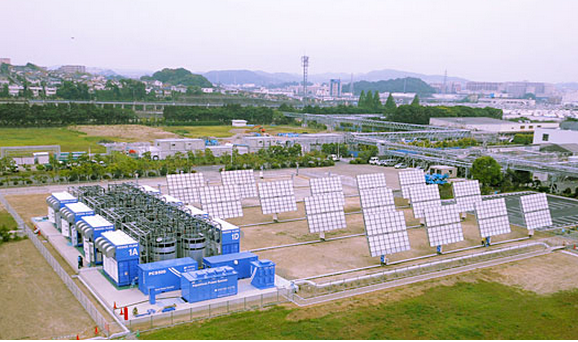
A Sumitomo Electric flow battery for energy storage of a solar PV plant. (Photo: Sumitomo Electric Co.)
Redox flow batteries – the energy storage breakthrough
The high demand for a reliable and cost-effective energy storage systems is reflected in the increased diversity of technologies for energy storage. Among different electrochemical storage systems, one of the most promising candidates are redox-flow batteries (RFBs). They could meet large-scale energy storage requirements scoring in high efficiency, low scale-up cost, long charge/discharge cycle life, and independent energy storage and power generation capacity.
Since this technology is still young, the development of commercially and economically viable systems demands:
improvement of the core components e.g. membranes with special properties,
improvement of energy efficiency
reduction in overall cost system.
Meeting demands for redox flow batteries
Two research teams in the United Kingdom, one from Imperial College and the other from the University of Cambridge, pursued a new approach to design the next generation of microporous membrane materials for the redox-flow batteries. They recently published their data in the well renown journal Nature Materials. Well-defined narrow microporous channels together with hydrophilic functionality of the membranes enable fast transport of salt ions and high selectivity towards small organic molecules. The new membrane architecture is particularly valuable for aqueous organic flow batteries enabling high energy efficiency and high capacity retention. Importantly, the membranes have been prepared using roll-to-roll technology and mesoporous polyacrylonitrile low-cost support. Hence, these innovative membranes could be cost effective.
As the authors reported, the challenge for the new generation RFBs is development of low-cost hydrocarbon-based polymer membranes that features precise selectivity between ions and organic redox-active molecules. In addition, ion transport in these membranes depends on a formation of the interconnected water channels via microphase separation, which is considered a complex and difficult-to-control process on molecular level.
The new synthesis concept of ion-selective membranes is based on hydrophilic polymers of intrinsic microporosity (PIMs) that enable fast ion transport and high molecular selectivity. The structural diversity of PIMs can be controlled by monomer choice, polymerization reaction and post-synthetic modification, which further optimize these membranes for RFBs.
Two types of hydrophilic PIM have been developed and tested: PIMs derived from Tröger’s base and dibenzodioxin-based PIMs with hydrophilic and ionizable amidoxime groups.
The authors consider their approach innovative because of
The application of PIMs to obtain rigid and contorted polymer chains resulting in sub-nanometre-sized cavities in microporous membranes;
The introduction of hydrophilic functional groups forming interconnected water channels to optimize hydrophilicity and ion conductivity;
The processing of the solution to produce a membrane of submicrometre thickness. This further reduces ion transport resistance and membrane production costs.
Ionic conductivity has been evaluated by the real-time experimental observations of water and ion uptake. The results suggest that water adsorption in the confined three-dimensional interconnected micropores leads to the formation of water-facilitated ionic channels, enabling fast transport of water and ions.
The selective ionic and molecular transport in PIM membranes was analyzed using concentration-driven dialysis diffusion tests. It was confirmed that new design of membranes effectively block large redox active molecules while enabling fast ion transport, which is crucial for the operation of organic RFBs.
In addition, long-term chemical stability, good electrochemical, thermal stability and good mechanical strength of the hydrophilic PIM membranes have been demonstrated.
Finally, it has been reported that the performance and stability tests of RFBs based on the new membranes, as well as of ion permeation rate and selectivity, are comparable to the performances based on a Nafion™ membranes as benchmark.
Biological systems can control water flow using channels in their membranes. This has many advantages, for example when cells need to regulate their osmotic pressure. Also artificial systems, e.g. in water treatment or in electrochemical cells, could benefit from it. Now, a group of materials researchers behind Dr. Zhou at the University of Manchester in the United Kingdom have developed a membrane that can electrically switch the flow of water.
As the researchers reported in the journal Nature, a sandwiched membrane of silver, graphene, and gold was fabricated. At a voltage of more than 2 V channels it opens its pores and water is immediately channeled through the membrane. The effect is reversible. To do this, the researchers used the property of graphene to form a tunable filter or even a perfect barrier to liquids and gases. New ‘smart’ membranes, developed using a low-cost form of graphene called graphene oxide, allow precise control of water flow by using an electrical current. The membranes can even be used to completely block water when needed.
To produce the membrane, the research group has embedded conductive filaments in the electrically insulating graphene oxide membrane. An electric current passed through these nanofilaments created a large electric field that ionizes the water molecules and thus controls the water transport through the graphene capillaries in the membrane.
At Frontis Energy we are excited about this new technology and can imagine numerous applications. This research makes it possible to precisely control water permeation from ultrafast flow-through to complete shut-off. The development of such smart membranes controlled by external stimuli would be of great interest to many areas of business and research alike. These membranes could, for instance, find application in electrolysis cells or in medicine. For medical applications, artificial biological systems, such as tissue grafts, enable a plenty of medical applications.
However, the delicate material consisting of graphene, gold, and silver nano-layers is still too expensive and not as resistant as our Nafion™ membranes. But unlike Nafion™ you can tune them. We stay tuned to see what is coming next.