Posted on

Smart fuel cells catalyzed by self-adjusting anodes improve water management

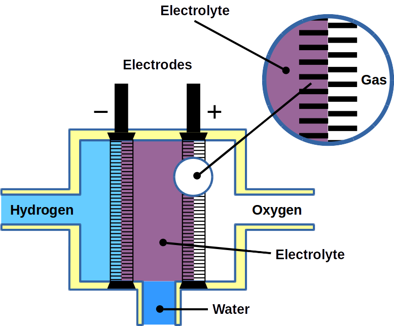
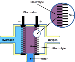
Hydrogen fuel cells are often regarded as a key element in the green energy transition. Their efficiency is double the thermochemical energy conversion of internal combustion engines. Hydrogen fuel cells convert the chemical energy of hydrogen and oxygen directly into electricity and water. Hence, water plays a central role in fuel cells. It supports ion transport and participates is product of the reaction itself. In an anion exchange membrane fuel cell (AEMFC), for the oxygen reduction reaction to take place, the water in the anode catalyst layer (ACL) must diffuse to the cathode catalyst layer (CCL). In summary, water management is required to remove water from the ACL for higher efficiency of hydrogen diffusion and to balance the water in the entire membrane electrode assembly (MEA).

Significant research efforts have been made to achieve conditions that is suitable for both the anode and cathode in AEMFC. Asymmetric humidification of reactant gases was proposed to be beneficial to achieve well equilibrated water balance between the two electrodes. At higher temperatures, excess anode water evaporates. It also causes deficiencies at the cathode which also requires water to function. To counteract this, a new system that controls the back pressure at the anode and cathode was introduced. However, external control mechanisms (active control) increase the complexity of the system control.

This is where a passive control system involving MEA modification comes into the picture. Moisture control in a fuel cells can be achieved by designing a suitable gas diffusion layer. Adopting different types of hydrophobic materials for the anode and hydrophilic for the cathode can improve overall fuel cell performance. Poly ethylene tetrafluoroethylene (PTFE) copolymer ion exchange membranes, such as Nafion™ have high water mobility. This property can help water back diffusion to avoid anode flooding while preventing dehydration of the cathode. Designing a gradient microstructure or ionomer content within the CCL could also be useful to improve cell performance and durability.

Recent research published in the journal Cell Reports Physical Science addresses these questions. The presented study was carried out to assess a multi-layer CCL design with the gradient capillary force which has a driving effect on water to solve the water balance problem of anodes in AEMFC. For the purpose of the study, platinum on carbon and platinum-ruthenium on carbon were selected as anode catalysts. Ruthenium increases the hydrogen oxidation reaction activity and possesses beneficial structural properties. Water management and performance of AEMFC would be influenced by the structure of the ACL.

Microstructure analysis of ACLs

ACLs composed of different layers of Pt/C and PtRu/C and a mixed version with a similar thickness of around 9-10 µm were analyzed with energy-dispersive X-ray spectroscopy (EDX).

Pt/C ACL had pores of less than 150 nm while PtRu/C catalysts pores ranged between 300-400 nm. The mixed ACL had a pore size <200 nm.

The researchers concluded that Pt/C and PtRu/C ACL had a stratified and gradient pore size distribution spanning across the anion exchange membrane and the gas diffusion layer. The mixed ACL, however, had a homogenous pore structure throughout the MEA.

Membrane electrode assembly using a polymer electrolyte membrane

Moisture adsorption and desorption behavior of ACLs

To investigate moisture adsorption and desorption, the change of the fuel cell’s moisture content was checked with regards to different levels of relative humidity.

It was observed that the moisture content level increased by up to 50% mass weight along with an increase in relative humidity from 20% to 80%.

With an extended equilibrium time for a relative humidity of 80%, the moisture content of Pt/PtRu and PtRu/Pt ACL began to decrease. This was evidence for the self-adjusting water management behavior.

Desorption at a relative humidity of 60% was done. The water content in ACL showed rapid adsorption and slow-release properties at each relative humidity setting.

Physical adjustment of water behavior was observed in PtRu/Pt ACLs. This was attributed to gradient nano-pores and promoted water transport when water was generated within the ACLs during the electrochemical reactions. It would facilitate fuel cells operation at high current density.

Fuel cell performance of ACLs

To assess the structural effect on water management during operation, fuel cell performance was investigated at different relative humidity and temperature levels.

With increasing relative humidity from 40% to 80%, an increase of the maximum power density was observed as well while the temperature remained constant at 50°C. This was due to higher ionic conductivity at high membrane hydration.

At relative humidity of 100%, a maximum power density of the Pt/PtRu MEA and the mixed MEA decreased, however. The inverted MEA version using PtRu/Pt an increase to 243 mW/cm2 was observed. This suggested that the moisture desorption ability of PtRu/Pt MEA promoted mass transfer during fuel cell operation.

At a temperature of 60°C and 100% relative humidity, the maximum power density of PtRu/Pt reached 252 mW/cm2.

A durability test was conducted for PtRu/Pt MEA. It showed that after continuous operation for more than 16 hours at 100 mA/cm2 the voltage drop was <4%.

Conclusion

It became clear from the tests that the PtRu/Pt anode catalyst layer with its homogenous layer had a better self-adjustment capability for fuel cell water management. The gradient nanopore structure of the catalyst layer made it possible to transport water through the capillary effect. Excess water at the anode could either be transported towards the cathode where it would be used for reaction or towards the gas diffusion layer for its removal prevented flooding. Moreover, this catalyst layer made from PtRu/Pt showed better performance abilities too.

At Frontis Energy we think that this could resolve the issues faced with water management in the fuel cells. Since it is a passive control system that involves modifying the design of the fuel cells internally, intricate external systems could be replaced or complemented. The study certainly helps future fuel cell automation as an interesting new aspect of fuel cell design was discovered that could make them smarter.

Reference: Self-adjusting anode catalyst layer for smart water management in anion exchange membrane fuel cells, Cell Reports Physical Science, Volume 2, Issue 3, 24 March 2021, 100377

Posted on

Rechargeable PEM fuel cell with hydrogen storage polymer

Energy-converting devices such as fuel cells are among the most efficient and clean alternative energy-producing sources. They have the potential to replace fossil-fuel-based power generators. More specifically, proton exchange membrane fuel cells (PEMFCs) are promising energy conversion devices for residential, transportation and portable applications owing to their high power density and efficiency at low operating temperatures (ca. 60–80 °C). For the complete approach, with electrolytic hydrogen renewable sources, PEM fuel cells can become one of the cleanest energy carriers. This is because water is the final product of such energy conversion systems. Currently, Nafion™ membranes are regularly used as hydrogen barriers in these fuel cells.

A Proton exchange membrane

Sufficient hydrogen gas supply is crucial for practical application of the PEMFC systems. Currently, expensive high-pressure tanks (70 MPa) are state-of-the-art for hydrogen storage. Besides cost, there are other drawbacks such as portability and safety. In order to address these issues, alternative hydrogen storage materials have been extensively investigated. For example, metal hydrides and organic hydride materials, can fix and release hydrogen via covalent bonding.

Now, Dr. Junpei Miyake and colleagues of the University of Yamanashi, Japan, have proposed an “all-polymer” rechargeable PEMFC system (RCFC). The work has been published in Nature Communications Chemistry. Their strategy was to apply a hydrogen-storage polymer (HSP) sheet (a solid-state organic hydride) as a hydrogen-storage medium inside the fuel cell. With this approach, the issues like toxicity, flammability and volatility as well as concerns related to other components such as the fuel reservoir, feed pump and vaporizer were solved. The HSP structure is based on fluorenol/fluorenone groups that take over hydrogen-storage functionality.

In order to test the performance of their HSP-based rechargeable fuel cell, the scientists attached the HSP sheet of the membrane electrode to the catalyst layer of the anode. At the same time, the cathode side was operated as in a regular PEMFC. The researchers reported that an iridium catalyst has been applied to the inside of the HSP sheet to improve the hydrogen-releasing and fixing processes.

Fuel cell operation, cycle performance and durability were tested using cycles of 6 periodic steps. At first, hydrogen was infused into HSP sheet for 2 h, followed by nitrogen gas flushing to remove hydrogen from the anode. Then, heating of the cell up to 80°C to initiated hydrogen release from the HSP sheet. Together with oxygen gas supplied to the cathode side the fuel cell produced constant electrical current.

The team demonstrated that their HSP sheet released 20%, 33%, 51%, or 96% of the total fixed hydrogen gas in 20, 30, 60, or 360 min, respectively. The temperature was 80°C in the presence of the iridium catalyst. Also, the iridium catalyst could absorb up to 58 mol% hydrogen, which was considerably lower than that stored in the HSP. The maximum operation time was approximately 10.2 s / mgHSP (ca. 509 s for 50 mg of HSP) at a constant current density of 1 mA / cm2. The RCFCs reached cycleability of least 50 cycles. In addition, the utilization of a gas impermeable sulfonated poly-phenylene membrane (SPP-QP, another type of PEM) turned out to be a good strategy to enhance the opration time of the RCFC.

The advantageous features of the reported RCFC system include better safety, easier handling and lower weight. These are perfect for example in mobile application such as fuel cell vehicles. However, for the improvement of the RCFC performance, hydrogen storage capacity and kinetics (H2-releasing/fixing reactions) as well as catalyst stability need further improvements.

Posted on

Promising hydrophilic membranes with fast and selective ion transport for energy devices

In addition to well-established Nafion™ membranes which are currently the best trade-off between high-performance and cost in proton exchange fuel cells (PEM), methanol fuel cells, electrolysis cells etc. As our energy resources are diversifying, there is a growing demand for efficient and selective ion-transport membranes for energy storage devices such as flow batteries.

A Sumitomo Electric flow battery for energy storage of a solar PV plant. (Photo: Sumitomo Electric Co.)

Redox flow batteries – the energy storage breakthrough

The high demand for a reliable and cost-effective energy storage systems is reflected in the increased diversity of technologies for energy storage. Among different electrochemical storage systems, one of the most promising candidates are redox-flow batteries (RFBs). They could meet large-scale energy storage requirements scoring in high efficiency, low scale-up cost, long charge/discharge cycle life, and independent energy storage and power generation capacity.

Since this technology is still young, the development of commercially and economically viable systems demands:

  • improvement of the core components e.g. membranes with special properties,
  • improvement of energy efficiency
  • reduction in overall cost system.

Meeting demands for redox flow batteries

Two research teams in the United Kingdom, one from Imperial College and the other from the University of Cambridge, pursued a new approach to design the next generation of microporous membrane materials for the redox-flow batteries. They recently published their data in the well renown journal Nature Materials. Well-defined narrow microporous channels together with hydrophilic functionality of the membranes enable fast transport of salt ions and high selectivity towards small organic molecules. The new membrane architecture is particularly valuable for aqueous organic flow batteries enabling high energy efficiency and high capacity retention. Importantly, the membranes have been prepared using roll-to-roll technology and mesoporous polyacrylonitrile low-cost support. Hence, these innovative membranes could be cost effective.

As the authors reported, the challenge for the new generation RFBs is development of low-cost hydrocarbon-based polymer membranes that features precise selectivity between ions and organic redox-active molecules. In addition, ion transport in these membranes depends on a formation of the interconnected water channels via microphase separation, which is considered a complex and difficult-to-control process on molecular level.

The new synthesis concept of ion-selective membranes is based on hydrophilic polymers of intrinsic microporosity (PIMs) that enable fast ion transport and high molecular selectivity. The structural diversity of PIMs can be controlled by monomer choice, polymerization reaction and post-synthetic modification, which further optimize these membranes for RFBs.

Two types of hydrophilic PIM have been developed and tested: PIMs derived from Tröger’s base and dibenzodioxin-based PIMs with hydrophilic and ionizable amidoxime groups.

The authors consider their approach innovative because of

  1. The application of PIMs to obtain rigid and contorted polymer chains resulting in sub-nanometre-sized cavities in microporous membranes;
  2. The introduction of hydrophilic functional groups forming interconnected water channels to optimize hydrophilicity and ion conductivity;
  3. The processing of the solution to produce a membrane of submicrometre thickness. This further reduces ion transport resistance and membrane production costs.

Ionic conductivity has been evaluated by the real-time experimental observations of water and ion uptake. The results suggest that water adsorption in the confined three-dimensional interconnected micropores leads to the formation of water-facilitated ionic channels, enabling fast transport of water and ions.

The selective ionic and molecular transport in PIM membranes was analyzed using concentration-driven dialysis diffusion tests. It was confirmed that new design of membranes effectively block large redox active molecules while enabling fast ion transport, which is crucial for the operation of organic RFBs.

In addition, long-term chemical stability, good electrochemical, thermal stability and good mechanical strength of the hydrophilic PIM membranes have been demonstrated.

Finally, it has been reported that the performance and stability tests of RFBs based on the new membranes, as well as of ion permeation rate and selectivity, are comparable to the performances based on a Nafion™ membranes as benchmark.

(Mima Varničić, 2020, photo: Wikipedia)

Posted on

Electrical energy storage

Electrical Energy Storage (EES) is the process of converting electrical energy from a power network into a form that can be stored for converting back to electricity when needed. EES enables electricity to be produced during times of either low demand, low generation cost, or during periods of peak renewable energy generation. This allows producers and transmission system operators (TSOs) the ability to leverage and balance the variance in supply/demand and generation costs by using stored electricity at times of high demand, high generation cost, and/or low generation capacity.
EES has many applications including renewables integration, ancillary services, and electrical grid support. This blog series aims to provide the reader with four aspects of EES:

  1. An overview of the function and applications of EES technologies,
  2. State-of-the-art breakdown of key EES markets in the European Union,
  3. A discussion on the future of these EES markets, and
  4. Applications (Service Uses) of EES.

Table: Some common service uses of EES technologies

Storage Category

Storage Technology

Pumped Hydro

Open Loop

Closed Loop

Electro-chemical

Batteries

Flow Batteries

Capacitors

Thermal Storage


Molten Salts

Heat

Ice

Chilled Water

Electro-mechanical

Compressed Air Energy Storage (CAES)

Flywheel

Gravitational Storage

Hydrogen Storage


Fuel Cells

H2 Storage

Power-to-Gas

Unlike any other commodities market, electricity-generating industries typically have little or no storage capabilities. Electricity must be used precisely when it is produced, with grid operators constantly balancing electrical supply and demand. With an ever-increasing market share of intermittent renewable energy sources the balancing act is becoming increasingly complex.

While EES is most often touted for its ability to help minimize supply fluctuations by storing electricity produced during periods of peak renewable energy generation, there are many other applications. EES is vital to the safe, reliable operation of the electricity grid by supporting key ancillary services and electrical grid reliability functions. This is often overlooked for the ability to help facilitate renewable energy integration. EES is applicable in all of the major areas of the electricity grid (generation, transmission & distribution, and end user services). A few of the most prevalent service uses are outlined in the Table above. Further explanation on service use/cases will be provide later in this blog, including comprehensive list of EES applications.

Area

Service Use / Case

Discharge Duration in h

Capacity in MW

Examples

Generation

Bulk Storage

4 – 6

1 – 500

Pumped hydro, CAES, Batteries

Contingency

1 – 2

1 – 500

Pumped hydro, CAES, Batteries

Black Start

NA

NA

Batteries

Renewables Firming

2 – 4

1 – 500

Pumped hydro, CAES, Batteries

Transmission & Distribution

Frequency & Voltage Support

0.25 – 1

1 – 10

Flywheels, Capacitors

Transmission Support

2 – 5 sec

10 – 100

Flywheels, Capacitors

On-site Power

8 – 16

1.5 kW – 5 kW

Batteries

Asset Deferral

3 – 6

0.25– 5

Batteries

End User Services

Energy Management

4 – 6

1 kW – 1 MW

Residential storage

Learn more about EES in the EU in the next post.

(Jon Martin, 2019)

Posted on

Fuel Cells

Fuel cells are a special type of galvanic cells. They can be fueled by solid, liquid, or gaseous fuel. The electrochemical oxidation of the fuel is coupled to energy gain, which is captured in form of electricity – as opposed to heat during chemical oxidation. Hence, fuel cells are direct energy converters with high efficiency. Most fuel cells achieve an energy conversion efficiency of 70-90%. If the conversion is 100%, no waste heat is produced. This ideal case of energy conversion is called ‘cold combustion’ which has been demonstrated for the first time in 1955 by Justi & Winsel. The fuel for this process is hydrogen gas, H2. It enters a porous nickel tube (gas diffusion electrode) where it is dissociated into protons and electrons according to:

H2 → 2 H+ + 2 e

Hydrogen fuel (H2) and oxygen (O2) are pumped into a fuel cell where two electrodes and the electrolyte fuse them to water.

During desorption, each H atom releases a proton (H+) and an electron (e). The electron is discharged onto the electrode, called anode, and the proton into the electrolyte. As a result of the dissociation process, the anode becomes negatively charged. On the second electrode, called cathode, oxygen gas, O2, is then charged with the electron and converted into O2− ions. The cathode becomes positively charged. Both electrodes are submerged in electrolytes which is in most cases a potassium hydroxide, KOH, solution of water. In the electrolyte, cations (H+) and anions (O2−) form water by chemical fusion. Theoretically, the efficiency is 92% accompanied by little waste heat – as opposed to normal combustion where heat of ~3,000ºC is produced.

2 H2 + O2 → H2O

Unlike heat power generators, fuel cells achieve high direct energy conversion efficiency because they avoid the additional step of heat generation. Besides shortcutting heat generation, fuel cells operate without mechanical parts and emit no noise, flue gas, or radioactivity, which puts them in focus of future developments. Due to their high energy efficiency and the high energy density of hydrogen, fuel cells are ideal for electric vehicles. In space flight, fuel cells were first used during Apollo Program between 1968 and 1972, in the Skylab Project 1973, the Apollo-Soyus Program, the Space Shuttle Program, and on board the International Space Station. There, they provide the electrical power for tools and water treatment. One benefit is that the final product of cold combustion in fuel cells is that water is the final product which is used by astronauts on their missions.

There are various types of fuel cells but all have in common that they consist of electrodes for fuel and O2 activation, and electrolytic conductors between these electrodes. Recent variations of fuel cells include methane fuel cells and microbial fuel cells. Due to the high activation energy of methane, methane fuel cells usually operate at high temperature using solid electrolytes. Microbial fuel cells, use microbes as anodic catalyst and organic matter in water as fuel. This makes them ideal for wastewater treatment.

Posted on

A Graphene Membrane Becomes a Nano-Scale Water Gate

Biological systems can control water flow using channels in their membranes. This has many advantages, for example when cells need to regulate their osmotic pressure. Also artificial systems, e.g. in water treatment or in electrochemical cells, could benefit from it. Now, a group of materials researchers behind Dr. Zhou at the University of Manchester in the United Kingdom have developed a membrane that can electrically switch the flow of water.

As the researchers reported in the journal Nature, a sandwiched membrane of silver, graphene, and gold was fabricated. At a voltage of more than 2 V channels it opens its pores and water is immediately channeled through the membrane. The effect is reversible. To do this, the researchers used the property of graphene to form a tunable filter or even a perfect barrier to liquids and gases. New ‘smart’ membranes, developed using a low-cost form of graphene called graphene oxide, allow precise control of water flow by using an electrical current. The membranes can even be used to completely block water when needed.

To produce the membrane, the research group has embedded conductive filaments in the electrically insulating graphene oxide membrane. An electric current passed through these nanofilaments created a large electric field that ionizes the water molecules and thus controls the water transport through the graphene capillaries in the membrane.

At Frontis Energy we are excited about this new technology and can imagine numerous applications. This research makes it possible to precisely control water permeation from ultrafast flow-through to complete shut-off. The development of such smart membranes controlled by external stimuli would be of great interest to many areas of business and research alike. These membranes could, for instance, find application in electrolysis cells or in medicine. For medical applications, artificial biological systems, such as tissue grafts, enable a plenty of medical applications.

However, the delicate material consisting of graphene, gold, and silver nano-layers is still too expensive and not as resistant as our Nafion™ membranes. But unlike Nafion™ you can tune them. We stay tuned to see what is coming next.

(Illustration: University of Manchester)