Posted on

Producing liquid bio-electrically engineered fuels from CO2

At Frontis Energy we have spent much thought on how to recycle CO2. While high value products such as polymers for medical applications are more profitable, customer demand for such products is too low to recycle CO2 in volumes required to decarbonize our atmosphere to pre-industrial levels. Biofuel, for example from field crops or algae has long been thought to be the solution. Unfortunately, they require too much arable land. On top of their land use, biochemical pathways are too complex to understand by the human brain. Therefore, we propose a different way to quickly reach the target of decarbonizing our planet. The proce­dure begins with a desired target fuel and suggests a mi­crobial consortium to produce this fuel. In a second step, the consortium will be examined in a bio-electrical system (BES).

CO2 can be used for liquid fuel production via multiple pathways. The end product, long-chain alcohols, can be used either directly as fuel or reduced to hydrocarbons. Shown are examples of high level BEEF pathways using CO2 and electricity as input and methane, acetate, or butanol as output. Subsequent processes are 1, aerobic methane oxida­tion, 2, direct use of methane, 3 heterotrophic phototrophs, 4, acetone-butanol fermentation, 5, heterotrophs, 6, butanol di­rect use, 7, further processing by yeasts

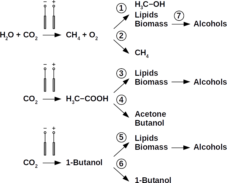
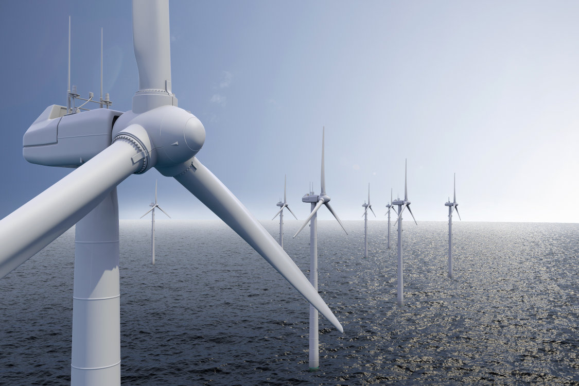
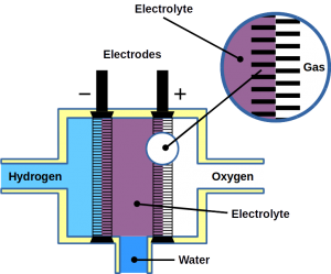
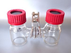
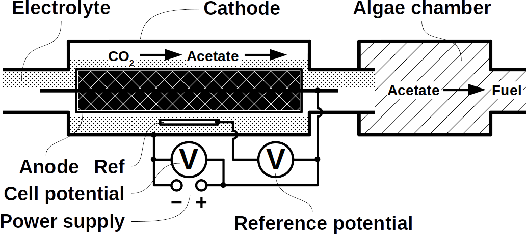
Today’s atmospheric CO2 imbalance is a consequence of fossil carbon combus­tion. This real­ity requires quick and pragmatic solutions if further CO2 accu­mulation is to be prevented. Direct air capture of CO2 is moving closer to economic feasibility, avoid­ing the use of arable land to grow fuel crops. Producing combustible fuel from CO2 is the most promis­ing inter­mediate solution because such fuel integrates seamlessly into existing ur­ban in­frastructure. Biofuels have been ex­plored inten­sively in re­cent years, in particular within the emerging field of syn­thetic biol­ogy. How­ever tempt­ing the application of genetically modified or­ganisms (GMOs) ap­pears, non-GMO technology is easier and faster to im­plement as the re­quired microbial strains al­ready exist. Avoiding GMOs, CO2 can be used in BES to produce C1 fu­els like methane and precursors like formic acid or syngas, as well as C1+ com­pounds like ac­etate, 2-oxybut­yrate, bu­tyrate, ethanol, and butanol. At the same time, BES inte­grate well into urban in­frastructure without the need for arable land. However, except for meth­ane, none of these fuels are readily com­bustible in their pure form. While elec­tromethane is a com­mercially avail­able al­ternative to fossil natu­ral gas, its volumetric energy den­sity of 40-80 MJ/m3 is lower than that of gasoline with 35-45 GJ/m3. This, the necessary technical modifications, and the psychological barrier of tanking a gaseous fuel make methane hard to sell to automobilists. To pro­duce liq­uid fuel, carbon chains need to be elongated with al­cohols or better, hy­drocarbons as fi­nal prod­ucts. To this end, syngas (CO + H2) is theoreti­cally a viable option in the Fischer-Tropsch process. In reality, syngas pre­cursors are ei­ther fossil fu­els (e.g. coal, natural gas, methanol) or biomass. While the for­mer is ob­viously not CO2-neu­tral, the latter com­petes for arable land. The di­rect con­version of CO2 and electrolytic H2 to C1+ fuels, in turn, is catalyzed out by elec­troactive microbes in the dark (see title figure), avoid­ing food crop com­petition for sun-lit land. Unfortunately, little re­search has been under­taken beyond proof of con­cept of few electroactive strains. In stark con­trast, a plethora of metabolic studies in non-BES is avail­able. These studies often pro­pose the use of GMOs or complex or­ganic sub­strates as precur­sors. We propose to systemati­cally identify metabolic strategies for liquid bio-electrically engineered fuel (BEEF) production. The fastest approach should start by screening meta­bolic data­bases using es­tablished methods of metabolic modeling, fol­lowed by high throughput hypothesis testing in BES. Since H2 is the intermediate in bio-electrosynthesis, the most efficient strategy is to focus on CO2 and H2 as di­rect pre­cursors with as few in­termediate steps as pos­sible. Scala­bility and energy effi­ciency, eco­nomic feasibil­ity that is, are pivotal elements.

First, an electrotrophic acetogen produces acetate, which then used by heterotrophic algae in a consecutive step.

The biggest obstacle for BEEF production is lacking knowledge about pathways that use CO2 and electrolytic H2. This gap exists despite metabolic data­bases like KEGG and more recently KBase, making metabolic design and adequate BEEF strain selection a guessing game rather than an educated ap­proach. Nonetheless, metabolic tools were used to model fuel pro­duction in single cell yeasts and various prokaryotes. In spite of their shortcomings, metabolic data­bases were also employed to model species interactions, for example in a photo-het­erotroph consor­tium using software like ModelSEED / KBase (http://mod­elseed.org/), RAVEN / KEGG and COBRA. A first sys­tematic at­tempt for BEEF cul­tures produci­ng acetate demonstrated the usability of KBase for BES. This research was a bottom-up study which mapped ex­isting genomes onto existing BEEF consor­tia. The same tool can also be em­ployed in a top-down ap­proach, starting with the desired fuel to find the re­quired or­ganisms. Some possi­ble BEEF organisms are the following.

Possible pathways for BEEF production involving Clostridium, 3, or heterotrophic phototrophs, 7, further processing by yeasts

Yeasts are among the microorganisms with the greatest potential for liquid biofuel production. Baker’s yeast, (Saccha­romyces cerevisiae) is the most promi­nent exam­ple. While known for ethanol fermentat­ion, yeasts also produce fusel oils such as bu­tane, phenyl, and amyl derivate aldehy­des and alco­hols. Unlike ethanol, which is formed via sugar fer­mentation, fusel oil is syn­thesized in branched-off amino acid pathways followed by alde­hyde reduction. Many en­zymes involved in the re­duction of aldehydes have been identified, with al­cohol dehydro­genases be­ing the most commonly ob­served. The corre­sponding reduc­tion reactions require reduced NADH⁠ but it is not known whether H2 pro­duced on cathodes of BES can be in­volved.
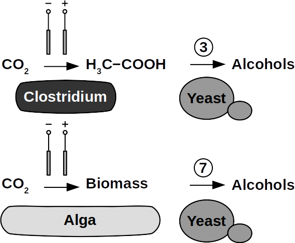
Clostridia, for example Clostridium acetobutylicum and C. carboxidivo­rans, can pro­duce alcohols like butanol, isopropanol, hexanol, and ketones like acetone from complex sub­strates (starch, whey, cel­lulose, etc. ) or from syngas. Clostridial me­tabolism has been clarified some time ago and is dif­ferent from yeast. It does not necessar­ily require com­plex precursors for NAD+ reduction and it was shown that H2, CO, and cath­odes can donate elec­trons for alcohol production. CO2 and H2 were used in a GMO clostridium to produce high titers of isobu­tanol. Typi­cal representa­tives for acetate produc­tion from CO2 and H2 are C. ljungdahlii, C. aceticum, and Butyribac­terium methy­lotrophicum. Sporo­musa sphaeroides pro­duces acetate in BES. Clostridia also dominated mixed cul­ture BESs converting CO2 to butyrate. They are therefore prime targets for low cost biofuel production. Alcohols in clostridia are produced from acetyl-CoA. This reaction is re­versible, al­lowing ac­etate to serve as substrate for biofuel production with extra­cellular en­ergy sup­ply. Then, en­ergy con­servation, ATP syn­thesis that is, can be achieved from ethanol electron bifurca­tion or H2 oxida­tion via respi­ration. While pos­sible in anaero­bic clostridia, it is hitherto unknown whether elec­tron bifurca­tion or res­piration are linked to alcohols or ke­tone synthesis.
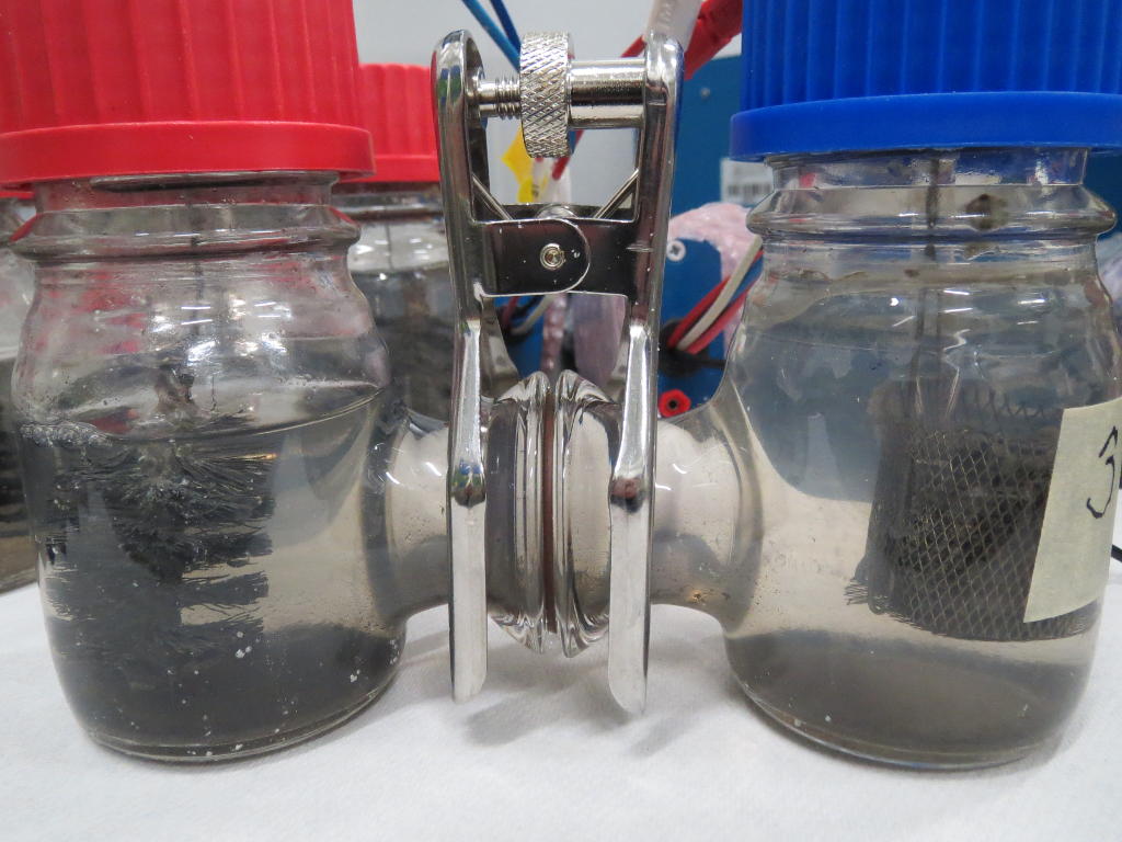
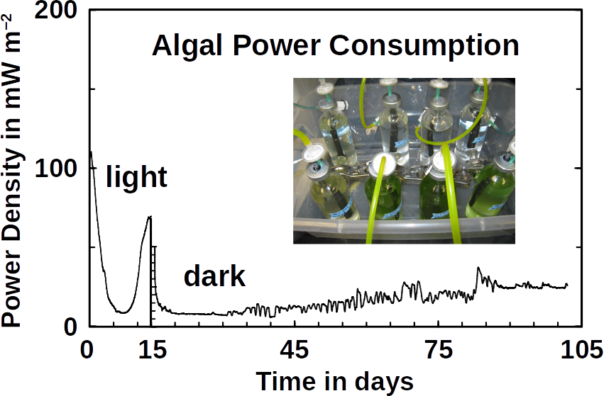
Phototrophs like Botryococcus produce C1+ biofuels as well. They synthesize a number of different hydro­carbons including high value alkanes and alkenes as well as terpenes. However, high titers were achieved by only means of ge­netic engineering, which is economically not feasible in many countries due to regulatory constrains. Moreover, aldehyde dehy­dration/deformylation to alkanes or alkenes requires molecular oxygen to be present. Also the olefin path­way of Syne­chococcus depends on molecular oxygen with the cytochrome P450 involved in fatty acid de­carboxylation. The presence of molecular oxygen affects BES performance due to immediate product degrada­tion and unwanted cathodic oxygen reduction. In contrast, our own preliminary experi­ments (see title photo) and a corrosion experi­ment show that algae can live in the dark using electrons from a cath­ode. While the en­zymes in­volved in the production of some algal biofuels are known (such as olefin and alde­hyde de­formylation), it is not known whether these pathways are connected to H2 utilization (perhaps via ferredox­ins). Such a con­nection would be a promising indicator for the possibility of growing hydrocar­bon produc­ing cyanobacteria on cathodes of BES and should be examined in future research.
At Frontis Energy we believe that a number of other microorganisms show potential for BEEF production and these deserve further investi­gation. To avoid GMOs, BES compatible co-cultures must be identified via in silico meta­bolic reconstruc­tion from existing databases. Possible inter-species intermediates are unknown but are prerequisite for suc­cessful BES operation. Finally, a techno-economical assessment of BEEF pro­duction, with and with­out car­bon taxes, and compared with chemical methods, will direct future research.

Posted on

Ammonia energy storage #2

Recently, we reported on plans by Australian entrepreneurs and their government to use ammonia (NH3) to store excess wind energy. We proposed converting ammonia and CO2 from wastewater into methane gas (CH4), because it is more stable and easier to transport. The procedure follows the chemical equation:

8 NH3 + 3 CO2 → 4 N2 + 3 CH4 + 6 H2O

Now we have published a scientific article in the online magazine Frontiers in Energy Research where we show that the process is thermodynamically possible and does indeed occur. Methanogenic microbes in anaerobic digester sludge remove the hydrogen (H2) formed by electrolysis from the reaction equilibrium. As a result, the redox potentials of the oxidative (N2/NH3) and the reductive (CO2/CH4) half-reactions come so close that the process becomes spontaneous. It requires a catalyst in the form of wastewater microbes.

Pourbaix diagram of ammonium oxidation, hydrogen formation and CO2 reduction. At pH 7 and higher, the oxidation of ammonium coupled to methanogenesis becomes thermodynamically possible.

To prove our idea, we first searched for the right microbes that could carry out ammonia oxidation. For our experiments in microbial electrolysis cells we used microorganisms from sediments of the Atlantic Ocean off Namibia as starter cultures. Marine sediments are particularly suitable because they are relatively rich in ammonia, free from oxygen (O2) and contain less organic carbon than other ammonia-rich environments. Excluding oxygen is important because it used by ammonia-oxidizing microbes in a process called nitrification:

2 NH3+ + 3 O2 → 2 NO2 + 2 H+ + 2 H2O

Nitrification would have caused an electrochemical short circuit, as the electrons are transferred from the ammonia directly to the oxygen. This would have bypassed the anode (the positive electron accepting electrode) and stored the energy of the ammonia in the water − where it is useless. This is because, anodic water oxidation consumes much more energy than the oxidation of ammonia. In addition, precious metals are often necessary for water oxidation. Without producing oxygen at the anode, we were able to show that the oxidation of ammonium (the dissolved form of ammonia) is coupled to the production of hydrogen.

Oxidation of ammonium to nitrogen gas is coupled to hydrogen production in microbial electrolysis reactors. The applied potentials are +550 mV to +150 mV

It was important that the electrochemical potential at the anode was more negative than the +820 mV required for water oxidation. For this purpose, we used a potentiostat that kept the electrochemical potential constant between +550 mV and +150 mV. At all these potentials, N2 was produced at the anode and H2 at the cathode. Since the only source of electrons in the anode compartment was ammonium, the electrons for hydrogen production could come only from the ammonium oxidation. In addition, ammonium was also the only nitrogen source for the production of N2. As a result, the processes would be coupled.

In the next step, we wanted to show that this process also has a useful application. Nitrogen compounds are often found in wastewater. These compounds consist predominantly of ammonium. Among them are also drugs and their degradation products. At the same time, 1-2% of the energy produced worldwide is consumed in the Haber-Bosch process. In the Haber-Bosch process N2 is extracted from the air to produce nitrogen fertilizer. Another 3% of our energy is then used to remove the same nitrogen from our wastewater. This senseless waste of energy emits 5% of our greenhouse gases. In contrast, wastewater treatment plants could be net energy generators. In fact, a small part of the energy of wastewater has been recovered as biogas for more than a century. During biogas production, organic material from anaerobic digester sludge is decomposed by microbial communities and converted into methane:

H3C−COO + H+ + H2O → CH4 + HCO3 + H+; ∆G°’ = −31 kJ/mol (CH4)

The reaction produces CO2 and methane at a ratio of 1:1. Unfortunately, the CO2 in the biogas makes it almost worthless. As a result, biogas is often flared off, especially in places where natural gas is cheap. The removal of CO2 would greatly enhance the product and can be achieved using CO2 scrubbers. Even more reduced carbon sources can shift the ratio of CO2 to CH4. Nevertheless, CO2 would remain in biogas. Adding hydrogen to anaerobic digesters solves this problem technically. The process is called biogas upgrading. Hydrogen could be produced by electrolysis:

2 H2O → 2 H2 + O2; ∆G°’ = +237 kJ/mol (H2)

Electrolysis of water, however, is expensive and requires higher energy input. The reason is that the electrolysis of water takes place at a relatively high voltage of 1.23 V. One way to get around this is to replace the water by ammonium:

2 NH4+ → N2 + 2 H+ + 3 H2; ∆G°’ = +40 kJ/mol (H2)

With ammonium, the reaction takes place at only 136 mV, which saves the respective amount of energy. Thus, and with suitable catalysts, ammonium could serve as a reducing agent for hydrogen production. Microorganisms in the wastewater could be such catalysts. Moreover, without oxygen, methanogens become active in the wastewater and consume the produced hydrogen:

4 H2 + HCO3 + H+ → CH4 + 3 H2O; ∆G°’ = –34 kJ/mol (H2)

The methanogenic reaction keeps the hydrogen concentration so low (usually below 10 Pa) that the ammonium oxidation proceeds spontaneously, i.e. with energy gain:

8 NH4+ + 3 HCO3 → 4 N2 + 3 CH4 + 5 H+ + 9 H2O; ∆G°’ = −30 kJ/mol (CH4)

This is exactly the reaction described above. Bioelectrical methanogens grow at cathodes and belong to the genus Methanobacterium. Members of this genus thrive at low H2 concentrations.

The low energy gain is due to the small potential difference of ΔEh = +33 mV of CO2 reduction compared to the ammonium oxidation (see Pourbaix diagram above). The energy captured is barely sufficient for ADP phosphorylationG°’ = +31 kJ/mol). In addition, the nitrogen bond energy is innately high, which requires strong oxidants such as O2 (nitrification) or nitrite (anammox) to break them.

Instead of strong oxidizing agents, an anode may provide the activation energy for the ammonium oxidation, for example when poised at +500 mV. However, such positive redox potentials do not occur naturally in anaerobic environments. Therefore, we tested whether the ammonium oxidation can be coupled to the hydrogenotrophic methanogenesis by offering a positive electrode potential without O2. Indeed, we demonstrated this in our article and have filed a patent application. With our method one could, for example, profitably remove ammonia from industrial wastewater. It is also suitable for energy storage when e.g. Ammonia synthesized using excess wind energy.

Posted on

Wind Energy

Wind energy is short for the conversion of energy captured from wind to electrical or mechanical energy. Wind power turbines produce electrical energy and windmills produce mechanical energy. Other forms for wind energy conversion are wind pumps which use wind energy to pump water or sails which drive sail boats.

The cheapest US energy prices by source and county, Source: Energy Institute, University of Texas Austin

Since its first use on sail boats, wind energy is wide spread. Windmills have been used for more than 2,000 years as source of mechanical energy. The Scotsman James Blythe was the first who demonstrated the transformation of wind energy into electrical energy. As wind energy is a renewable source of energy, electrical energy generated by wind turbines is a clean and sustainable form of energy. Wind energy is often also cheaper than natural gas, for example throughout the entire American Midwest, as shown by the Energy Institute of University of Texas, Austin. It is therefore not surprising that wind energy is one of the fastest growing markets in the renewable energy sector worldwide. In 2015, 38% of all renewable energy in the United States and the European Union was generated by wind turbines.

Wind and solar energy production in the US and Canada in 2015. Sources: EIA, Statistics Canada

More efficient than single wind turbines is the use of wind parks where clusters of large turbines constantly generate electrical power. There are two kinds of wind parks, on-shore and off-shore wind parks. Off-shore wind parks are often more expensive but do not use valuable farmland as it is often the case for on-shore wind parks. However, wind parks on farmland can be a valuable addition for farmers seeking an extra income.

Wind and solar energy production in the European Union and the Euro-zone in 2015. WSH is the fraction of renewable energy of the European energy market. “Hydro” is the fraction of hydro power an Wasserkraft. Source, Eurostat
Posted on

Fuel Cells

Fuel cells are a special type of galvanic cells. They can be fueled by solid, liquid, or gaseous fuel. The electrochemical oxidation of the fuel is coupled to energy gain, which is captured in form of electricity – as opposed to heat during chemical oxidation. Hence, fuel cells are direct energy converters with high efficiency. Most fuel cells achieve an energy conversion efficiency of 70-90%. If the conversion is 100%, no waste heat is produced. This ideal case of energy conversion is called ‘cold combustion’ which has been demonstrated for the first time in 1955 by Justi & Winsel. The fuel for this process is hydrogen gas, H2. It enters a porous nickel tube (gas diffusion electrode) where it is dissociated into protons and electrons according to:

H2 → 2 H+ + 2 e

Hydrogen fuel (H2) and oxygen (O2) are pumped into a fuel cell where two electrodes and the electrolyte fuse them to water.

During desorption, each H atom releases a proton (H+) and an electron (e). The electron is discharged onto the electrode, called anode, and the proton into the electrolyte. As a result of the dissociation process, the anode becomes negatively charged. On the second electrode, called cathode, oxygen gas, O2, is then charged with the electron and converted into O2− ions. The cathode becomes positively charged. Both electrodes are submerged in electrolytes which is in most cases a potassium hydroxide, KOH, solution of water. In the electrolyte, cations (H+) and anions (O2−) form water by chemical fusion. Theoretically, the efficiency is 92% accompanied by little waste heat – as opposed to normal combustion where heat of ~3,000ºC is produced.

2 H2 + O2 → H2O

Unlike heat power generators, fuel cells achieve high direct energy conversion efficiency because they avoid the additional step of heat generation. Besides shortcutting heat generation, fuel cells operate without mechanical parts and emit no noise, flue gas, or radioactivity, which puts them in focus of future developments. Due to their high energy efficiency and the high energy density of hydrogen, fuel cells are ideal for electric vehicles. In space flight, fuel cells were first used during Apollo Program between 1968 and 1972, in the Skylab Project 1973, the Apollo-Soyus Program, the Space Shuttle Program, and on board the International Space Station. There, they provide the electrical power for tools and water treatment. One benefit is that the final product of cold combustion in fuel cells is that water is the final product which is used by astronauts on their missions.

There are various types of fuel cells but all have in common that they consist of electrodes for fuel and O2 activation, and electrolytic conductors between these electrodes. Recent variations of fuel cells include methane fuel cells and microbial fuel cells. Due to the high activation energy of methane, methane fuel cells usually operate at high temperature using solid electrolytes. Microbial fuel cells, use microbes as anodic catalyst and organic matter in water as fuel. This makes them ideal for wastewater treatment.

Posted on

Corrosion

Corrosion is the chemical attack on a material leading eventually to its destruction if not stopped. It is caused by electrolytes, gases, solutions, or smelt. Corrosion occurs in different forms depending on the material under corrosive attack and the attacking agent. On metals, iron, for instance, its most visible manifestation is aerial or localized rust, such as needle holes in the surface. Crystalline corrosion of metals follows grain boundaries on surfaces. Corrosion is highly accelerated if the corroding material is in electrolytical contact with a more noble material. If this electrolytical contact is a liquid or humid substance, then corrosion is further accelerated. The reason is that the corroding material acts as anode (local cell) of a galvanic cell. Mechanical strain can accelerate corrosion as well.

A simple galvanic cell. The metal on the left side acts as anode and is dissolved into metal ions (M+). On the cathode water is transformed to hydrogen gas.

Corrosion protection is accomplished by coating the vulnerable material with corrosion resistant dense films. Such coating can be other metals such as zinc or chrome, as well as glazing, for example enamel. Protective paint is a wide-spread measure and is accomplished by adding pigments such as red (minium) or white lead, or organic substances. Tight plastic wrap is used as well. Iron is protected through transformation into stainless steel by adding chrome, nickel, etc.

The sacrificial anode is not a dissolving metal but soil or sewer organics. Microbes destroy these organics and produce CO2

If the material is exposed to water permanently, cathodic protection is frequently employed. To accomplish cathodic protection, the vulnerable material is connected to sacrificial anodes such as rods or plates that dissolve over time. Alternatively, directed current is used in many applications. Our patent pending solution provides a microbial anode that uses organic matter in soil or sewer as sacrificial anode. Instead of dissolving the metal, organic matter is degraded by microbes.

If a potentiostat is added to the galvanic cell, cathodic protection can be tailored to the protected material or the organics.

Besides metals, natural (wood, silk) and artificial polymers (plastics, rubber) can corrode as well. Softwood is generally more resistant than hardwood. Weak acids usually do no harm to wood. However, corrosion protection of wood is accomplished by painting or soaking it using protective agents. Artificial polymers rarely corrode as quickly as metals and if they do, a protective agent is mixed into the polymer formula at the time of its synthesis.

Posted on

Bioenergy

Bioenergy is renewable energy derived from biomass. Biomass is organic material that was produced by living organisms. Each type of biomass was once converted into chemical energy using sunlight and then stored.

Since biomass is stored chemical energy, it can be burned directly. Biofuels can be produced from biomass in solid, liquid or gaseous form. Bio-electricity is both the direct use of biomass and the conversion of biomass into oils, biogas or other fuels for power generation.

Wood that is burned to make fire is another example of biomass. Wood is the world’s most widely used biofuel. Ethanol is also a popular biofuel. It is produced by fermentation of sugars. The process is the same as in alcoholic fermentation for the production of beer or wine. Usually, yeasts carry out fermentation, but other microorganisms, such as clostridia are capable of producing alcohols and other volatile organics as well.

While combustion of biomass produces about the same amount of CO2 as fossil fuels, biofuels are produced in the present day and their combustion does not release additional CO2 into the atmosphere. Biofuels can also be used as fuel additives to reduce carbon emissions from gasoline prices. But there are also vehicles that are powered mainly by biofuels. Bioethanol is widespread in the United States and Brazil, while more biodiesel is produced in the European Union.

Posted on

Nanomaterials in bio-electrical systems could improve performance

Since Professor Potter’s discovery of the ability of microbes to turn organic molecules into electricity using microbial fuel cells (MFC) more than a century ago (Potter MC, 1911, Proc Roy Soc Lond Ser B 84:260–276), much research was done to improve the performance. Unfortunately, this did not not produce an economically viable technology. MFCs never made it out of the professors’ class rooms. This may change now that we have advanced nanomaterials available.

The testing of nanomaterials in bio-electrical systems has experienced a Cambrian explosion. The focus usually was on electrodes, membranes, and in the electrolyte with infinite possibilities to find high performing composites. The benefits of such materials include a large surface area, cost savings, and scalability. All are required to successfully commercialize bio-electrical systems. The large-scale commercial application could be wastewater treatment. In our recently published literature survey we discovered that there is no common benchmark for performance, as it is usual in photovoltaics or for batteries. To normalize our findings, we used dollar per peak power capacity as ($/Wp) as it is standard in photovoltaics. The median cost for air cathodes of MFCs is $4,700 /Wp ($2,800 /m²). Platinum on carbon (Pt/C) and carbon nanofibers are the best performing materials with $500 /Wp (Pt/C $2,800 /m²; nanofibers $2,000 /m²).

We found that carbon-based nanomaterials often deliver performance comparable to Pt/C. While MFCs are still far away from being profitable, microbial electrolysis cells already are. With these new carbon-based nanomaterials, MFCs however, are moving closer to become an economic reality. Graphene and carbon nanotubes are promising materials when they are combined with minerals such as manganese or iron oxides. However, the price of graphene is still too expensive to let MFCs become an economic reality in wastewater treatment. The costs of microbial electrolysis, however, are already so low that it is a serious alternative to traditional wastewater treatment as we show in the featured image above. For high strength wastewater, a treatment plant can in fact turn into a power plant with excess power being offered to surrounding neighborhoods. Reducing the costs of microbial electrolysis is accomplished by using a combination of cheap steel and graphite.

Relationship between MEC reactor capacity and total electrode cost including anode and cathode. Errors are standard deviations of four different tubular reactor designs. Anodes are graphite granules and cathodes are steel pipes


Graphite, in turn, is the precursor of graphene, a promising material for MFC electrodes. When graphite flakes are reduced to a few graphene layers, some of the most technologically important properties of the material are greatly improved. These include the overall surface and the elasticity. Graphene is therefore a very thin graphite. Many manufacturers of graphene use this to sell a material that is really just cheap graphite. In the journal Advanced Materials Kauling and colleagues published a systematic study of graphene from sixty manufacturers and find that many high-priced graphene products consist mainly of graphite powder. The study found that less than 10% of the material in most products was graphene. None of the tested products contained more than 50% graphene. Many were heavily contaminated, most likely with chemicals used in the production process. This can often lead to a material having catalytic properties which would not have been observed without contamination, as reported by Wang and Pumera.

There are many methods of producing graphene. One of the simplest is the deposition on a metallic surface, as we describe it in our latest publication:

Single-layer graphene (SLG) and multilayer graphene (MLG) are synthesized by chemical vapor deposition (CVD) from a carbon precursor on catalytic metal surfaces. In a surface-mediated CVD process, the carbon precursor, e.g. Isopropyl alcohol (IPA) is decomposed on the metal surface, e.g. Cu or Ni. In order to control the number of graphene layers formed, the solubility of the carbon precursor on the metal catalyst surface must be taken into account. Due to the low solubility of the precursor in Cu, SLG can be formed. It is difficult to grow SLG on the surface of a metal with a high affinity for the precursor.

Protocol:
The protocol is a cheap, safe and simple method for the synthesis of MLG films by CVD in 30-45 minutes in a chemistry lab. A nickel foil is submersed in acetic acid for etching and then transferred to an airtight quartz tube. The same protects the system from ambient oxygen and water vapor. Nitrogen gas is bubbled through the IPA and the resulting IPA saturated gas is passed through the closed system. The exhaust gases are washed in a beaker with a water or a gas wash bottle. The stream is purged for 5 minutes at a rate of about 50 cc/min. As soon as the flame reaches a Meker burner 575-625 °C, it is positioned under the nickel foil, so that sufficient energy for the formation of graphene is available. The flame is extinguished after 5-10 minutes to stop the reaction and to cool the system for 5 minutes. The graphene-coated Ni foil is obtained.

But how thin must graphite flakes be to behave as graphene? A common idea supported by the International Organization for Standardization (ISO) is that flakes with more than ten graphene layers consist essentially of graphite. Thermodynamics say that each atomic layer in a flake with ten or fewer layers at room temperature behaves as a single graphene crystal. In addition, the stiffness of the graphite flakes increases with the layer thickness, which means that thin graphene flakes are orders of magnitude more elastic than thicker graphite flakes.

Unfortunately, to actually use graphene in bioelectric reactors, you still have to make it yourself. The ingredients can be found in our DIY Shop.

 
Posted on

Better heat exchangers for concentrated solar power

Solar thermal systems are a good example of the particle-wave dualism expressed in Planck’s constant h: E = hf. Where h is the Planck constant, f is the frequency of the light and E is the resulting energy. Thus, the higher the frequency of the light, the higher the amount of energy. Solar thermal metal collectors transform the energy of high-frequency light by generating them to an abundance of low-frequencies through Compton shifts. Glass or ceramic coatings with high visible and UV transmittance absorb the low frequency light generated by the metal because they effectively absorb infrared light (so-called heat blockers). The efficiency of the solar thermal system improves significantly with increasing size, which is also the biggest advantage of such systems compared to photovoltaic generators. One disadvantage, however, is the downstream transformation of heat into electricity with the help of heat exchangers and turbines − a problem not only in solar thermal systems.

To provide the hot gas (supercritical CO2) to the turbines, heat exchangers are necessary. These heat exchangers transfer the heat energy generated by a power plant to the working fluid in a heat engine (usually a steam turbine) that converts the heat into mechanical energy. Then, the mechanical energy is used to generate electricity. These heat exchangers are operated at ~800 Kelvin and could be more efficient if the temperature were at >1,000 Kelvin. The entire process of converting heat into electricity is called a power cycle and is a critical process in power generation by solar thermal plants. Obviously, heat exchangers are pivotal elements in this process.

Ceramics are a great material material for heat exchanger because they can withstand extreme temperature fluctuations. However, unlike metals, ceramics are not easy to shape. Relatively coarse shapes, in turn, are made quickly and easily. In contrast, metals can be easily formed and have a high mechanical strength. Metals and ceramics have been valued for centuries for their distinctive properties. For example, bronze and iron have good impact resistance and are so malleable that they have been made into complex shapes such as weapons and locks. Ceramics, like those used to make pottery, have been formed into simpler shapes. Their resistance to heat and corrosion made ceramics a valued material. A new composite of metal and ceramic (a so-called cermet) combines these properties in amazing ways. A research group led by Mario Caccia reported now in the prestigious journal Nature about a cermet with properties that makes it usable for heat exchangers in solar thermal systems.

The history of such composites goes back to the middle of the 20th century. The advent of jet engines has created a need for materials with high resistance to heat and oxidation. On top of that, they had to deal with rapid temperature changes. Their excellent mechanical strength, which often surpassed that of existing metals, was highly appreciated by the newly created aerospace industry. Not surprisingly, the US Air Force funded more research into the production of cermets. Cermets have since been developed for multiple applications, but in most cases have been used for small parts or surfaces. The newly released composite withstands extreme temperatures, high pressures and rapid temperature changes. It could increase the efficiency of heat exchangers in solar thermal systems by 20%.

To produce the composite, the authors first produced a precursor, which was subject to further processing, comparable to potting the unfired version of a clay pot. The authors compacted tungsten carbide powder into the approximate shape of the desired article (the heat exchanger) and heated it at 1,400 °C for 2 minutes to bond the parts together. They then further processed this porous preform to produce the desired final shape.

Next, the authors heated the preform in a chemically reducing atmosphere (a mixture of 4% hydrogen in argon) at 1,100 °C. At the same temperature, they immersed the preform in a tank of liquid zirconium and copper (Zr2Cu). Finally, the preform was removed by heating to 1,350 °C. In this process, the zirconium displaces the tungsten from the tungsten carbide, producing zirconium carbide (ZrC) as well as tungsten and copper. The liquid copper is displaced from the ZrC matrix as the material solidifies. The final object consists of ~58% ZrC ceramic and ~36% tungsten metal with small amounts of tungsten carbide and copper. The beauty of the method is that the porous preform is converted into a non-porous ZrC / tungsten composite of the same dimensions. The total volume change is about 1-2%.

The elegant manufacturing process is complemented by the robustness of the final product. At 800 °C, the ZrC / tungsten cermet conducts heat 2 to 3 times better than nickel based iron alloys. Such alloys are currently used in high-temperature heat exchangers. In addition to the improved thermal conductivity, the mechanical strength of the ZrC / tungsten composite is also higher than that of nickel alloys. The mechanical properties are not affected by temperatures of up to 800 ° C, even if the material has previously been subjected to heating, e.g. for cooling cycles between room temperature and 800 °C. In contrast, iron alloys, e.g. stainless steels, and nickel alloys loose at least 80% of their strength.

(Photo: Wikipedia)

Posted on

A Durable Aluminum-Air-Battery

Non-rechargeable batteries, which depend on a reaction between aluminum and oxygen, can store significantly more energy than conventional lithium-ion batteries. The biggest limitation of such aluminum-air batteries is their short shelf life. An improved battery design could help eliminate this limitation. Aluminum and air batteries are based on the property of aluminum to corrode, which is also their weak spot:

4 Al + 3 O2 + 6H2O → 4 Al (OH)3

While an aluminum-air battery is not used, its electrodes corrode causing unwanted discharge. This self-discharge drastically shortens the shelf life of the battery. Brandon Hopkins, of the Massachusetts Institute of Technology in Cambridge, and his colleagues developed an aluminum-air battery that uses a conventional electrolyte during operation. When stored, however, the electrolyte is replaced by oil. Their article was recently published in the journal Science.

The new battery reaches a storage capacity of almost 900 Wh / kg. This makes the prototype comparable to other aluminum-air batteries. In contrast, the new corrosion protection extends the storage time 10,000-fold. The authors suggest that such a battery could be used in long-range drones and grid-independent power generation. At Frontis Energy, we believe that batteries with high storage capacity and durability can be used almost anywhere, for example for sensors and other applications.

(Photo: George Hodan)

Posted on

White Christmas, going … gone

In Germany, we seem to remember White Christmas from fairy tales only. Now there is also scientific evidence that winter snow cover in Europe is thinning. Thanks to global warming, the snow cover decrease accelerated

The research group behind Dr. Fontrodona Bach of the Royal Netherlands Meteorological Institute in De Bilt analyzed snow cover and climate data from six decades from thousands of weather stations across Europe. The researchers found that the mean snow depth, with the exception of some local extremely cold spots, has been decreasing since 1951 at 12% per decade. The researchers recently published their research results in the journal Geophysical Research Letters. The amount of “extreme” snow cover affecting local infrastructure has declined more slowly.

The observed decline, which accelerated after the 80s, is the result of a combination of rising temperatures and the impact of climate change on precipitation. The decreasing snow cover can reduce the availability of fresh water during the spring melt, the authors noted.

(Photo: Doris Wulf)