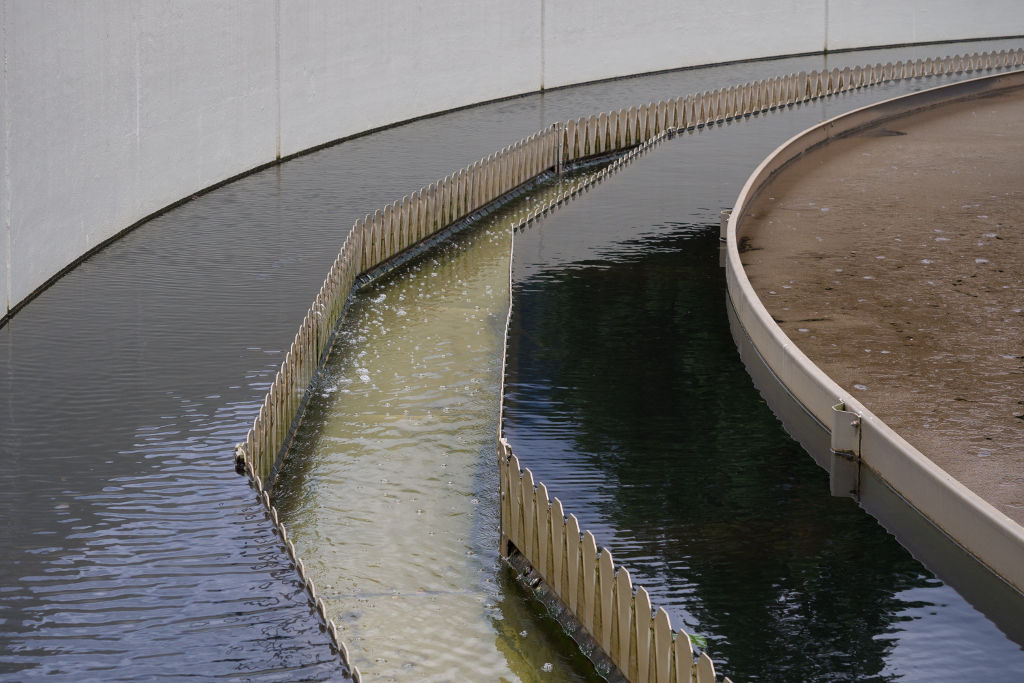
Hazardous compound removal from sewage such as organic matter and nitrogen makes wastewater treatment an energy intensive process. For example, treating activated sludge requires blowing oxygen or air into raw, unsettled sewage. This aeration significantly increases the cost of the wastewater treatment. About 5 kWh per kilogram nitrogen are required for aeration depending on the plant. The cost associated with energy consumption makes uof approximately EUR 500,000 per year in an average European wastewater treatment plant. This is up to one-third of the total operational costs of WWTP. It is therefore obvious that nitrogen removal from wastewater must become more economical.
Alternative approach: Microbial electrochemical technology
The conventional way of removing nitrogen is a cascade of nitrification and denitrification reactions. Nitrification that is, aerobic ammonium oxidation to nitrite and nitrate is carried out by ammonia-oxidizing bacteria. Subsequent denitrification is the reduction of nitrate to nitrogen gas (N2). In addition to the costly aeration process, the remaining intermediate products as nitrite and nitrate require further effluent treatment.
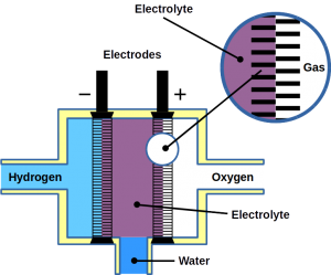
Instead of expensive pumping of oxygen into the wastewater, bioelectrical systems could accomplish the same result at a much lower cost. In such systems, an electron accepting anode is used as electron acceptor for microbial ammonium oxidation instead of oxygen, making aeration obsolete.
Complete conversion of ammonium to nitrogen gas
We previously reported the use of such an bio-electrical system to remove ammonia from wastewater in fed-batch reactors. Now, researchers of the University of Girona reported proof-of-concept on a novel technology. Their bioelectrical system is a complete anoxic reactor that oxidizes ammonium to nitrogen gas in continuous mode. The dual-chamber reactor nitrifies and denitrifies and ultimately removes nitrogen from the system.
The electricity-driven ammonium removal was demonstrated in continuously operated one-liter reactor at a rate of ~5 g / m3 / day. A complex microbial community was identified with nitrifying bacteria like Nitrosomonas as key organism involved anoxic ammonium oxidation.
From an application perspective, comparison between bioelectrical systems and aeration in terms of performance and costs is necessary. The researchers reported that the same removal range and treatment of the similar amounts of nitrogen was achieved but that their bioelectrical system converted almost all ammonium to dinitrogen gas (>97%) without accumulation of intermediates. Their system required about 0.13 kWh per kilogram nitrogen energy at a flow rate of 0.5 L / day. Using a bioelectrical system consumes 35 times less energy compared with classic aeration (~5 kWh per kilogram). At the same time, no hazardous intermediates like nitrite or NOx gases are formed.
Unveiling microbial-electricity driven ammonium removal
The new article also indicated potential clues for microbial degradation pathway that may lead to better understanding of the underlying processes of anoxic ammonium removal in bioelectrical systems.
The proposed nitrogen removal pathway was the bioelectrical oxidation of ammonia to nitrogen monoxide, possibly carried out by a microbe named Achromobacter. That was supposedly followed by the reduction of the nitrogen monoxide to nitrogen gas, a reaction that could have been performed by Denitrasisoma. Alternatively, three other secondary routes were considered: bioelectrical oxidation followed by anammox, or without nitrogen monoxide directly to N2. Some sort of electro-anammox may also be possible.
At Frontis Energy, we believe that the direct conversion of ammonium to nitrogen gas through the reversal of nitrogen fixation is a possibility as nitrogen fixation genes are ubiquitous in the microbial world and it would generate the universal bio-currency ATP rather than consuming it.
It was shown that Achromobacter sp. was the most abundant microbe (up to 60%, according to sequence reads) in the mixed community. However, anammox species (Candidatus Kuenenia and Candidatus Anammoximicrobium) and denitrifying bacteria (Denitratisoma sp.) have been also detected in the reactor.
Two possible electroactive reactions were identified: hydroxylamine and nitrite oxidation, reinforcing the role of the anode as the electron acceptor for ammonium oxidation. Data obtained from nitrite and nitrate tests suggested that both, denitrification and anammox based reactions could take place in the system to close the conversion.
As a result, ammonium was fully oxidized to nitrogen gas without accumulated intermediates. Taking it all together, it has been shown that ammonium can be removed in bioelectrical system operated in continuous flow. However, further reactor and process engineering combined with better understanding of the underlying microbial and electrochemical mechanisms will be needed for process scale up.
Experimental system set-up
- The inoculum consisted of a 1:1 mix of biomass obtained from nitritation reactor and an aerobic nitrification reactor of an urban treatment plant
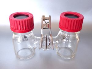
- The reactor design was constructed of two 1 L rectangular chambers comprising an anode and cathode compartment
- The separator, an anion exchange membrane, was used to minimize the diffusion of ammonium to the cathode compartment
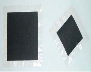
- The anode and cathode chambers were filled with granular graphite as electrode support
- Ag/AgCl reference electrode was used in the anode compartment
- Two graphite rods were placed as current collectors in each chamber
- The system was operated in batch and semi-continuous mode
Image: 5056468 / Pixabay