Most of the world’s energy needs are currently served by fossil fuels. The International Energy Agency (IEA) annual projection indicates that the global energy demand will increase twice by 2040, mostly in emerging markets and developing economies.
To meet increasing global energy demands and to replace depleting fossil fuels, policy makers believe that alternative clean and renewable energy sources are the best solution. Such renewable energy sources can be electricity for solar, wind or geothermal energy as well as hydroelectric power. The latter, however, has reached a certain degree of saturation in fully industrialized countries.
While solar and wind energy are available in most places of the world at more or less reasonable cost, their biggest disadvantage is that they are intermittent, difficult to store and transport, and difficult to tank in cars, planes and ships. Converting solar and wind energy in hydrogen gas could be an elegant way out of this dilemma as the fuel’s resource can be abundant water. Diversifying the energy mix by adding hydrogen at acceptable cost may prove more efficient with a lower environmental footprint as compared to other fuels. Hence, the interest for water electrolysis and fuel cells is constantly growing.
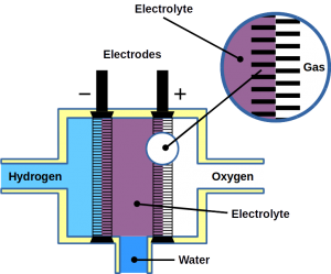
Most of today’s hydrogen is produced through steam reforming of natural gas. However, it can also be made from water electrolysis. Electrolysis is two-electrode reactions: the hydrogen evolution reaction (HER) at the cathode and the oxygen evolution reaction (OER) at the anode.
Fuel cells reverse the reaction and harvest electricity produced by fusing the hydrogen and oxygen atoms back together to obtain water. While there are different types of fuel cells, those commonly used with hydrogen as fuel are polymer electrolyte membrane fuel cells, or PEMFC. The PEM acronym is also often used for proton exchange membranes, which can be made of polymers, for example Nafion™. In PEMFC, energy is liberated through the hydrogen oxidation reaction (HOR) at the anode and oxygen reduction reaction (ORR) at the cathode. To become economically feasible, there are still technical challenges of water electrolyzers and fuel cells to overcome. Some technical problems result in serious system degradation.
A study published in Nature Communications by researcher of Technical University Berlin and the Korea Institute of Science and Technology, suggests using a novel iridium electrocatalyst with multifunctional properties and remarkable reversibility. While iridium also is precious and one of the platinum group metals, the novel Ir-catalyst was designed for the processes where electrochemical reactions change rapidly, such as the voltage reversal of water electrolysis and PEMFC systems. This would integrate the two energy conversion systems in one and therefore be a great economical benefit over existing solutions.
Challenges
Unexpectedly changing operating conditions such as a sudden shut-down of water electrolysis result in increased hydrogen electrode potentials which lead to degradation hydrogen producing electrodes.
In fuel cells, fuel starvation can occur at the anode, leading to voltage reversal. Ultimately, this causes degradation of fuel cell components such as the catalyst support, gas diffusion layer and flow field plates. It has been proposed to introduce a water oxidation catalyst to the anode of the PEMFcs in order to promote OER since it is the reaction that competes with the carbon corrosion reaction.
Design of a unique iridium-based multifunctional catalyst
For the study, a crystalline multifunctional iridium nanocatalyst has been designed considering the mentioned challenges in water electrolysis and fuel cell operation.
The reason why an iridium-based material has been selected is its remarkable OER activity as well as good HER and HOR catalytic activity. It is a superior material for anodes and cathodes in electrolyzers and for anodes of PEMFC. For comparisons, the researchers synthesized two catalysts using the modified impregnation method: carbon-supported IrNi alloy nanoparticles with high crystallinity (IrNi/C-HT) and with low crystallinity (IrNi/C-LT).
The findings indicated that the surface of IrNi/C-HT had reversibly converted between a metallic character and an oxidic IrNiOx character. Under OER operation that is, anodic water oxidation, the crystalline nanoparticles form an atomically-thin IrNiOx layer. This oxide layer reversibly transforms into metallic iridium when returning towards more cathodic potentials. The reversal allows the catalyst to return to its high HER and HOR activity.
The experiments also revealed that the performance of IrNi/C-LT sharply decrease after carrying out the OER. The catalyst degradation was due to the irreversible destruction of the amorphous IrNiOx surface.
In situ/operando X-ray absorption near edge structure (XANES) and depth-resolving X-ray photoelectron spectroscopy (XPS) profiles, suggested that the thin layers of IrNiOx possess an increase in the number of d-band holes during OER, due to which catalyst IrNi/C-HT exhibited excellent OER activity. As expected, under HER conditions, the thin IrNiOx layer was reversibly converted to metallic surface. The mechanistic study of the reversible catalytic activity of the IrNiOx layer has been additionally analyzed by electrochemical flow-cell using inductively coupled plasma-mass spectrometry (ICP-MS). The results demonstrate that the reversible IrNiOx layers come from a dissolution and re-deposition mechanism.
In addition, the performance and catalytic reversibility of synthetized electrocatalysts were used to perform HOR and OER in a real electrochemical device and tested under fuel starvation of the PEMFC. Using voltage reversal, the fuel cell was converted into an electrolyzer.
Fuel starvation experiments were conducted in a single PEM fuel cell built using IrNi/C-HT and IrNi/C-LT as the catalytically active components in the anode catalyst layer. The initial fuel cell performance of IrNi/C-LT and -HT was lower than that of the commercial Pt/C catalyst due to the lower HOR and metal composition.
Further results demonstrate that IrNi/C-HT catalyst retained its bifunctional catalytic activity, reversibing between HER and OER in a real device. This approach promoted the reversibility of nanocatalysts, which enable a variety of electrochemical reactions and can be used as catalysts to resist the reverse voltage in fuel cells and water electrolysis systems.
At Frontis Energy, we are looking forward to adding the novel iridium catalyst to our Fuel Cell Shop as soon as it becomes available.
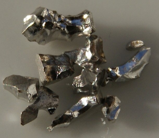
Photo: Iridium / Wikipedia